


Ulysses HISCALE Data Analysis Handbook
A17.5 LAN Spare - CD Analog Crosstalk
Document Reference: Memo from D. E. Fort to R. E. Gold, August 29, 1984
Crosstalk tests were performed on the CD Analog SN003 board by injecting energy signals into the C and D channels one at a time and monitoring the response of the other channel. The following results were obtained:
1) Crosstalk into the linear C channel (CO) tends to come from the edges of the [WAC]1 logic pulse. It is therefore nearly constant for all signals in the D channel which are above threshold, and is approximately 25 keV. This coupling between the [WAC]1 logic pulse and CO may explain the observed correlation of noise counts in D1 (which activates [WAC]1 and CO on the flight unit.
(1[WAC] stands for not WAC.)
2) Crosstalk into the LOG C channel is only evident as an increase in the peak background level. (The LOG C channel has peak detect and hold circuitry which tends to make the output ratchet to the peak level of the channel noise.) The magnitude of the increase was negligible for D = 0 to 500 keV, and then gradually approached 30 keV over the range D = 500 keV to 5 MeV, where it remained fairly constant through D = 100 MeV. Signal levels of the valid events in the LOG C channel were not affected.
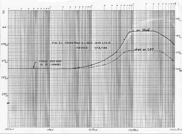
3) Crosstalk into the LOG D channel changed the apparent signal level of valid events. The observed effect on a 300 keV signal is plotted in Figure A17-12. This crosstalk was found to be primarily due to the physical proximity of the C linear channel to the LOG D channel, specifically of C57 to one of the log amp inputs. Placing a grounded shield over the body of C57 decreased the crosstalk to the values shown by the dashed curve in Figure A17-12.
Figure A17-12 Crosstalk - LOG C into LOG D
Except for the shield mentioned in item 3, little success in reducing these crosstalk levels has been achieved. What remains seems to be due to physical proximity rather than improper grounding or insufficient filtering, but attempts at better shielding have not been successful. Rerouting or shielding of selected wires from connector J17 is a possibility; however, it is felt that such changes in configuration should be deferred until system crosstalk checks have been made with the CD Analog board integrated with other subsystems.
Next: A17.6 Pile-up Effects in the LAN CD Analog Array
Return to Appendix 17 Table of Contents
Return to HISCALE List of Appendices
Return to Ulysses HISCALE Data Analysis Handbook Table of Contents
Updated 8/8/19, Cameron Crane
QUICK FACTS
Mission End Date: June 30, 2009
Destination: The inner heliosphere of the sun away from the ecliptic plane
Orbit: Elliptical orbit transversing the polar regions of the sun outside of the ecliptic plane