


Ulysses HISCALE Data Analysis Handbook
Appendix 18. Preliminary Solar Polar Magnet Study
A18.3 Data
In this section, the data is presented. Further discussion and results are presented in section 18.4.
For yoke SST-416/APL measurements of the magnetic field intensity were taken at separations of 0.10 inches in three planes (X, Y = +.1, Z), (X, Y = 0, Z) and (X, Y = -.1, Z). The data for Configuration I are presented in Figures A18-4 through A18-6 and for Configuration II in Figures A18-7 through A18-9. In the formats shown, the yoke outline indicates the outside dimensions to scale and the magnet outline is a projection onto the Y = 0 plane. Also shown in this format is the location of the solid-state detector. It can be seen that the peak field in the Y = 0 plane is 1840 Gauss at X = 0.7 inches from the front surface into the yoke.
 |
Figure A18-4 Yoke SST 416/APL, Configuration I, Magnets 1 and 2, Y=+0.1" |
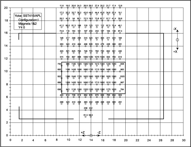 |
Figure A18-5 Yoke SST 416/APL, Configuration I, Magnets 1 and 2, Y=0 |
 |
Figure A18-6 Yoke SST 416/APL, Configuration I, Magnets 1 and 2, Y=-0.1" |
 |
Figure A18-7 Yoke SST 416/APL, Configuration II, Magnets 1 and 2, Y=+0.1" |
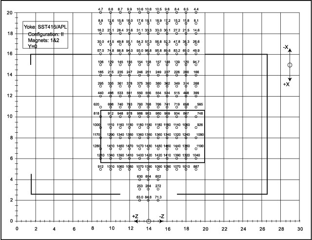 |
Figure A18-8 Yoke SST 416/APL, Configuration II, Magnets 1 and 2, Y=0 |
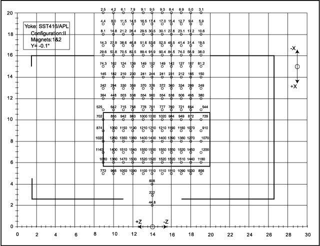 |
Figure A18-9 Yoke SST 416/APL, Configuration II, Magnets 1 and 2, Y=-0.1" |
The data is presented in a different format in Figures A18-10 through A18-12 for Configuration I and Figures A18-13 through A18-15 for Configuration II. This format is similar to the Voyager magnet presentations. Again, it can be seen that for Configuration I, the peak field is 1840 Gauss at X = 0.7 inches in the Y = 0 plane, while for configuration II the peak field is 1480 Gauss at X = 0.9 inches from the front plate. In general, the shape of the field intensity curve is similar to that of the Voyager magnets.
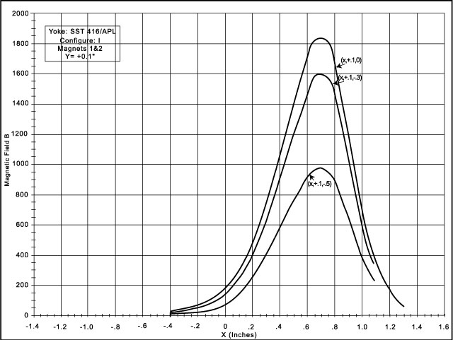 |
Figure A18-10 Yoke SST 416/APL, Configuration I, Magnets 1 and 2, Y=+0.1" , graphical form |
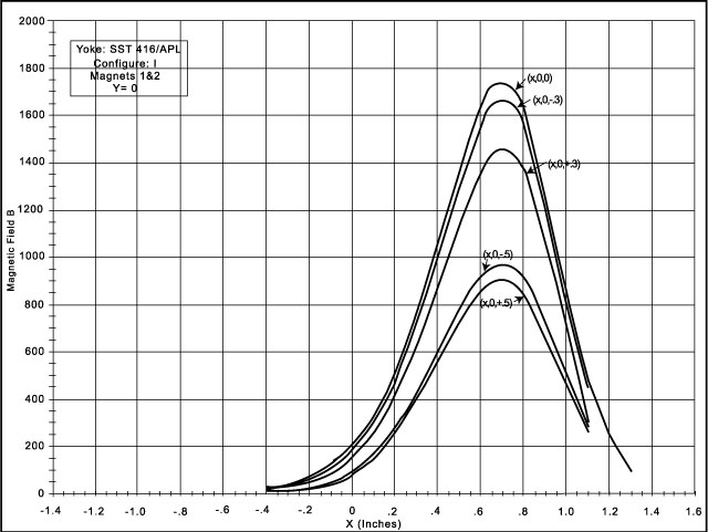 |
Figure A18-11 Yoke SST 416/APL, Configuration I, Magnets 1 and 2, Y=0, graphical form |
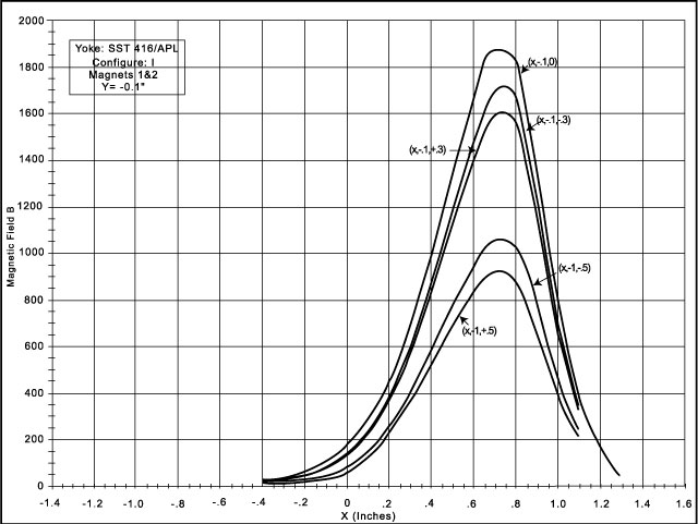 |
Figure A18-12 Yoke SST 416/APL, Configuration I, Magnets 1 and 2, Y=-0.1", graphical form |
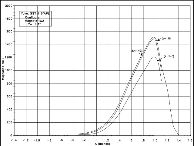 |
Figure A18-13 Yoke SST 416/APL, Configuration II, Magnets 1 and 2, Y=+0.1", graphical form |
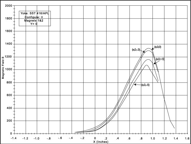 |
Figure A18-14 Yoke SST 416/APL, Configuration II, Magnets 1 and 2, Y=0, graphical form |
 |
Figure A18-15 Yoke SST 416/APL, Configuration II, Magnets 1 and 2, Y=-0.1", graphical form |
With this yoke in Configuration I, field intensities were measured along the centerline for different pairs of magnets. This data is presented in tabular form, rather than a graph, in Table A18-1.
Table A18-1 Solar Polar Magnetic Field Survey Yoke: SST416/APL (w/o hole). Magnet configuration I. Magnetic field (Gauss)
| Magnet Pairs | ||||||
| X (in) | Y (in) | Z (in) | 1 & 2 | 3 & 4 | 5 & 6 | 7 & 8 |
| -0.4 | 0 | 0 | 28 | 28.4 | 27.8 | 26.1 |
| -0.3 | 0 | 0 | 44 | 46.3 | 45.3 | 42.0 |
| -0.2 | 0 | 0 | 74 | 76.9 | 75.5 | 69.8 |
| -0.1 | 0 | 0 | 123 | 126 | 124 | 115 |
| 0 | 0 | 0 | 204 | 207 | 205 | 189 |
| 0.1 | 0 | 0 | 324 | 332 | 324 | 303 |
| 0.2 | 0 | 0 | 505 | 520 | 508 | 473 |
| 0.3 | 0 | 0 | 770 | 788 | 765 | 714 |
| 0.4 | 0 | 0 | 1080 | 1110 | 1070 | 1010 |
| 0.5 | 0 | 0 | 1420 | 1470 | 1390 | 1340 |
| 0.6 | 0 | 0 | 1720 | 1780 | 1660 | 1630 |
| 0.7 | 0 | 0 | 1840 | 1920 | 1760 | 1760 |
| 0.8 | 0 | 0 | 1720 | 1790 | 1610 | 1670 |
| 0.9 | 0 | 0 | 1330 | 1390 | 1210 | 1310 |
| 1.0 | 0 | 0 | 876 | 905 | 772 | 870 |
| 1.1 | 0 | 0 | 492 | 505 | 423 | 492 |
| 1.2 | 0 | 0 | 242 | 246 | 206 | 246 |
| 1.3 | 0 | 0 | 94.5 | 92.4 | 76.7 | 97.5 |
Yoke SST-416/UCB is similar to SST-416/APL except that it has a hole in the yoke which could accommodate a detector mount. Measurements of the magnetic field intensity were made only along the yoke centerline for Configuration I, but using the same magnet pair as used for the SST-416/APL yoke measurements. The data is presented in tabular form in Figure A18-16 and in graphical form in Figure A18-17. It can be seen that although the peak fields occur in the same location--0.7 inches from the front surface--the magnitude of SST-416/UCB is only 1750 Gauss compared to 1840 Gauss for SST-416/APL. This is probably due to an increase in leakage flux in the vicinity of the detector mounting hole and thereby a reduction in field in the center of the yoke.
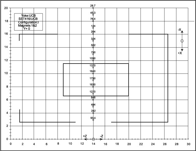 |
Figure A18-16 Yoke SST 416/UCB, Configuration I, Magnets 1 and 2, Y=0 |
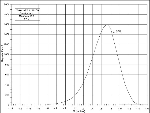 |
Figure A18-17 Yoke SST 416/UCB, Configuration I, Magnets 1 and 2, Y=0, graphical form |
Because of the high value of leakage flux from the stainless steel, a yoke of higher permeability material--Carpenter 49--was constructed. The initial C49 yoke had heavy wall thicknesses and no hole for a detector mount. The only magnetic field intensity measurements for the C49/APL yoke were made along the centerline in Configuration I. This data is presented in Figure A18-18 and in graphical form in Figure A18-19. It can be seen that the peak field value is 1890 Gauss, located at 0.7 inches from the front surface.
 |
Figure A18-18 Carpenter 49/APL, Configuration I, Magnets 1 and 2, Y=0 |
 |
Figure A18-19 Carpenter 49/APL, Configuration I, Magnets 1 and 2, Y=0, graphical form |
Next: A18.3.4 C49/Mod I
Return to Appendix 18 Table of Contents
Return to HISCALE List of Appendices
Return to Ulysses HISCALE Data Analysis Handbook Table of Contents
Updated 8/8/19, Cameron Crane
QUICK FACTS
Mission End Date: June 30, 2009
Destination: The inner heliosphere of the sun away from the ecliptic plane
Orbit: Elliptical orbit transversing the polar regions of the sun outside of the ecliptic plane