


Ulysses HISCALE Data Analysis Handbook
Appendix 18. Preliminary Solar Polar Magnet Study
A18.3 Data (continued)
The Carpenter 49 yoke was then machined down to a thinner wall section and a detector mount hole incorporated. This C49/Mod I yoke then had field intensity measurements made along the centerlines for Configuration I and Configuration II, presented in Figures A18-20 and A18-21 and graphically in Figures A18-22 and A18-23 respectively. As can be seen from the figures, the peak field value is 1870 Gauss at 0.7 inches from the front surface for Configuration I and 1480 Gauss at 0.9 inches for Configuration II.
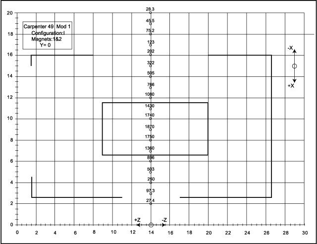 |
Figure A18-20 Carpenter 49, Configuration I, Magnets 1 and 2, Y=0 |
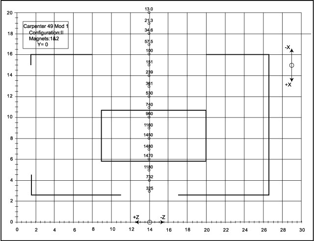 |
Figure A18-21 Carpenter 49, Configuration II, Magnets 1 and 2, Y=0 |
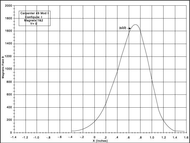 |
Figure A18-22 Carpenter 49, Configuration I, Magnets 1 and 2, Y=0, graphical form |
 |
Figure A18-23 Carpenter 49, Configuration II, Magnets 1 and 2, Y=0, graphical form |
Electron Beam: C49/Mod I was the first yoke to be tested at the NASA/GSFC accelerator. As mentioned previously, the yoke assembly was mounted such that the 0.125 inch diameter beam was targeted at some point in the X=0 (Y, Z plane) and the location of the beam image on the phosphor screen recorded. For each target position, the beam was rotated about a perpendicular to the yoke front surface. This procedure was repeated for several electron energies. The data is presented in Figures A18-24 through A18-33. The points indicate the center of the beam image with the bars indicating the extent of the image on the 0.9 inch diameter phosphor.
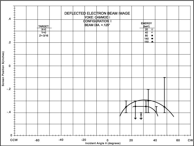 |
Figure A18-24 Carpenter 49, Mod I, Configuration I , z = -3/16 |
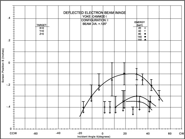 |
Figure A18-25 Carpenter 49, Mod I, Configuration I, z = 0 |
 |
Figure A18-26 Carpenter 49, Mod I, Configuration I, z = + 3/16 |
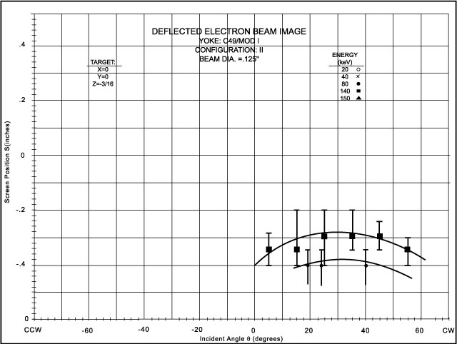 |
Figure A18-27 Carpenter 49, Mod I, Configuration II, y = 0, z = - 3/16 |
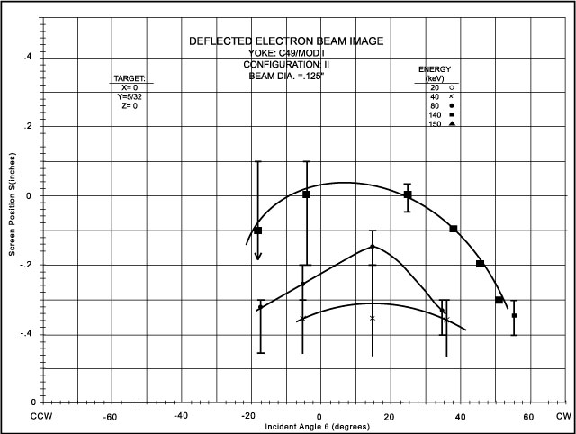 |
Figure A18-28 Carpenter 49, Mod I, Configuration II, y = 5/32, z = 0 |
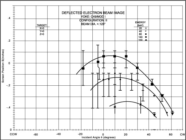 |
Figure A18-29 Carpenter 49, Mod I, Configuration II, y = 0, z = 0 |
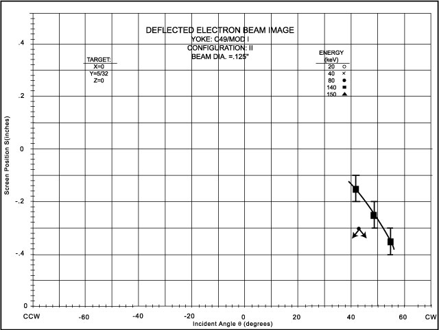 |
Figure A18-30 Carpenter 49, Mod I, Configuration II, y = -5/32, z = 0 |
|
|
Figure A18-31 Carpenter 49, Mod I, Configuration II, y = 5/32, z = 3/16 |
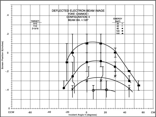 |
Figure A18-32 Carpenter 49, Mod I, Configuration II, y = 0, z = 3/16 |
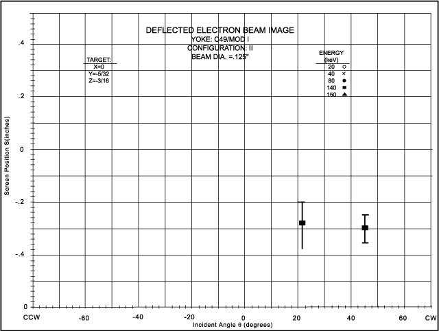 |
Figure A18-33 Carpenter 49, Mod I, Configuration II, y = -5/32, z = -3/16 |
Rough calculations of the electron trajectory support the above data. However, to more accurately determine the electron trajectories in the vicinity of the proposed detector location, the phosphor screen was displaced 0.375 inches further away and several of the electron beam runs repeated. This data is presented in Figure A18-34. An analysis of this data will be discussed in section A18.4.4.
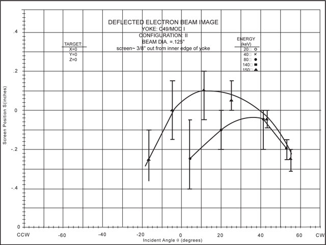 |
Figure A18-34 Carpenter 49, Mod I, Configuration II, y = 0, z = 0; screen ~3.8" from inner edge of yoke |
Next: A18.3.5 C49/Mod II
Return to Appendix 18 Table of Contents
Return to HISCALE List of Appendices
Return to Ulysses HISCALE Data Analysis Handbook Table of Contents
Updated 8/8/19, Cameron Crane
QUICK FACTS
Mission End Date: June 30, 2009
Destination: The inner heliosphere of the sun away from the ecliptic plane
Orbit: Elliptical orbit transversing the polar regions of the sun outside of the ecliptic plane