


Ulysses HISCALE Data Analysis Handbook
Appendix 9 Geometric Factor Study for the Deflected and Unscattered Electrons of HISCALE (Buckley MS Thesis)
A9.3 Chapter 3 - The Specific Problem (continued)
Figure A9-10 To determine the solid angle for a particular area element, the electron is placed at the starting coordinate with given starting angles, and its trajectory traced out one line segment at a time.
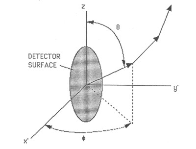
For example, for i = 1, the first detector element area, one can choose
θmin = 60º, θmax = 120º, fmin = 300º, fmax = 400º, and
Δθ = 2º, Δf = 2º.
These particular numbers will depend on the geometry of the telescope, as well as the detector area element one is using.
Next, one writes a program that loops through all the possible starting trajectories in the above range limits, i.e.,
θ = 60º, f = 300º,
θ = 62º, f = 300º,
.
.
.
θ = 60º, f = 302º,
.
.
.
A running total of all the trajectories that escape is tallied. The net result is the total number of trajectories, denoted npas, that make it out of the telescope for a given DAi and electron energy. The resulting DWi can be determined via
Return to HISCALE List of Appendices
Return to Ulysses HISCALE Data Analysis Handbook Table of Contents
Updated 8/8/19, Cameron Crane
QUICK FACTS
Mission End Date: June 30, 2009
Destination: The inner heliosphere of the sun away from the ecliptic plane
Orbit: Elliptical orbit transversing the polar regions of the sun outside of the ecliptic plane