


Ulysses HISCALE Data Analysis Handbook
Appendix 9 Geometric Factor Study for the Deflected and Unscattered Electrons of HISCALE (Buckley MS Thesis)
Through a trial and error method, all these parameters were adjusted to give a "best fit" to the magnetic field data given by Kohl. As mentioned earlier, Kohl had found the magnetic field strength for selected coordinates in the z = 0", .1", and -.1" planes. A test program has been written that computes the B-field at these calibration points using the parameters in FDMOD1.CMN, and compares them to the actual data values. Figure A9-22 shows the general position of the magnets and detector with respect to the calibration points, and summarizes how the results of this section will be presented.
Figure A9-22 Magnetic Intensity Map
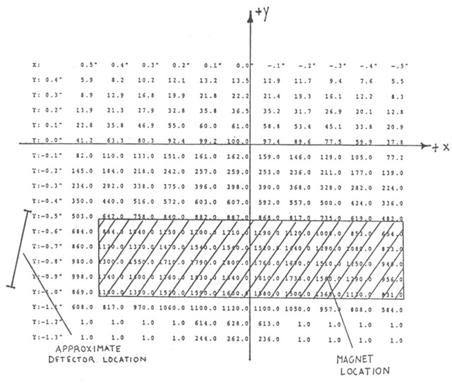
Listed on the following pages are the results for four different models, all using slightly different parameters. Listed first is the .CMN file used, then results for all three calibration planes. As one can see, the model is by no means perfect, but for the most important regions, the models usually fall within 10% of the experimental values of Kohl. One trouble area for the model is its inability to match the calibration points for extreme values in the x-direction. To obtain a better fit, one would have to go to a quadratic model as opposed to the more simple linear one.
Return to HISCALE List of Appendices
Return to Ulysses HISCALE Data Analysis Handbook Table of Contents
Updated 8/8/19, Cameron Crane
QUICK FACTS
Mission End Date: June 30, 2009
Destination: The inner heliosphere of the sun away from the ecliptic plane
Orbit: Elliptical orbit transversing the polar regions of the sun outside of the ecliptic plane