


Ulysses HISCALE Data Analysis Handbook
The HISCALE experiment consists of five apertures in two telescope assemblies mounted by means of two stub arms on a box containing all of the instrument electronics. The entire instrument is mounted on one corner of the spacecraft to give unimpeded fields of view to the telescopes. The HISCALE instrument viewing cones are shown in Figure 4.1. The entire system weighs 5.775 kg and consumes 4.0 W. An additional 7.5 W are available for heaters used in the telescopes and for thermal control of the log amplifiers and activation of the cover closure mechanisms.
Figure 4.1 HISCALE viewing cones with respect to Ulysses spin axis
The measurements required to fulfill the heliospheric science objectives cannot be made with a single charged-particle sensor. To attain the lowest energy of response over a wide variety of particle species with appropriate geometrical factors and angular resolution, HISCALE utilizes three distinct silicon solid-state detector systems. These are the Low-Energy Magnetic/Foil Spectrometers (LEMS/LEFS) and the Composition Aperture (CA). The CA system is sometimes referred to as the "WART" owing to its appearance. The LEMS/LEFS systems provide pulse-height-analyzed single-detector measurements with active anticoincidence. The CA system uses a multiparameter detection technique to provide measurements of ion composition in an energy range similar to those of LEMS/LEFS. The five separate detector systems are contained within two mechanical structures, LAN2A and LAN2B, as shown in Figure 4.2.
Figure 4.2 LAN2A and LAN2B simplified cross-sections
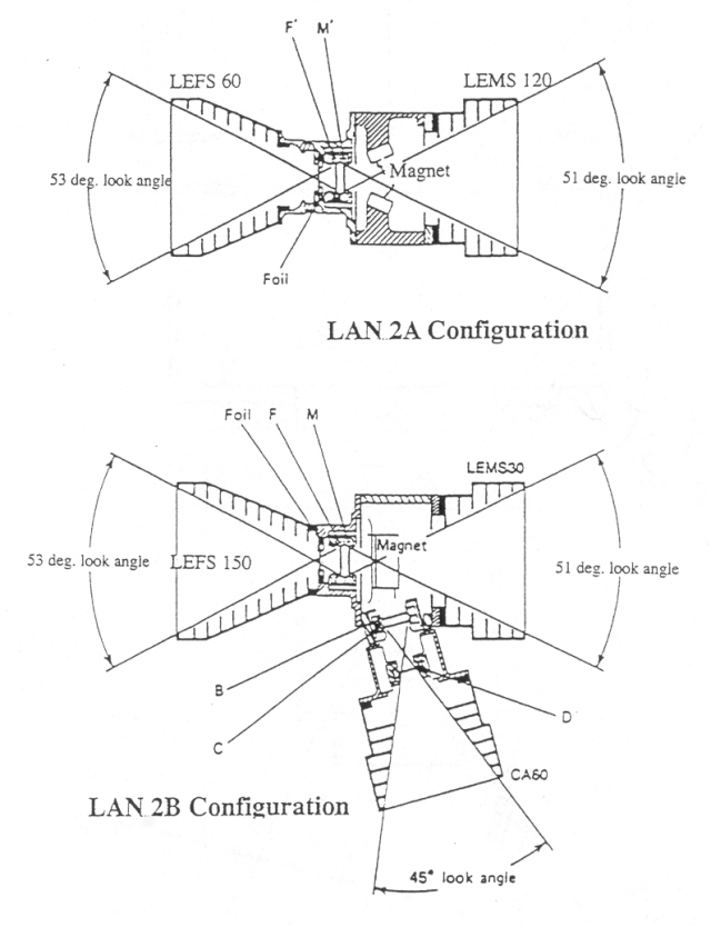
The individual telescopes are referred to as LEFS 60, LEFS 150, LEMS 30, LEMS 120, and CA 60, where the number indicates the inclination of the telescope axis with respect to the spacecraft spin axis. The opening angles and spin-axis orientations of the telescopes are shown schematically in Figure 4.1. The MF, M'F', and BC detector pairs (Tables 1.1 and 1.2) are identical (for ease of replacement); each consists of two equal 200 mm thick, totally depleted silicon surface barrier detectors. The D detector is a thin (5 mm) silicon detector of the epitaxial type.
In the LEMS30 and LEMS120 telescopes, electrons with energies below ~ 300 keV are swept away from detectors M and M' with a rare-earth magnet. The geometric factor for the ions measured by detectors M and M' is ~ 0.48 cm2 sr.
In the LEFS60 and LEFS150 telescopes, a thin (~ 0.35 mg/cm2) aluminized parylene foil (described in Section 4.2.2) prevents ions (~>350 keV) from reaching the F and F' detector, while electrons (~> 30 keV) can penetrate the foil with little energy loss. Both telescopes have a geometrical factor of ~ 0.48 cm2 sr.
In the LEMS 30 telescope the magnetically-deflected electrons are counted by a separate detector B. Section 4.9 in the following pages gives the calculated electron trajectories and resultant geometrical factors (~ 0.14 cm2 sr).
The CA telescope uses detectors D and C as shown in Figure 4.2 as a DE vs. E telescope, with the B detector operating in anticoincidence. The geometrical factor for the DC`B combination is 0.24 cm2 sr. The logic and discrete energy channels for the CA telescope are described in Section 4.4. In addition, the HISCALE data system (Section 4.5) uses a rotating priority scheme to identify those individual particle events whose energy loss signals in detectors D and C are pulse-height-analyzed.
Figure 4.3a LAN2A cross section detail (M'F')
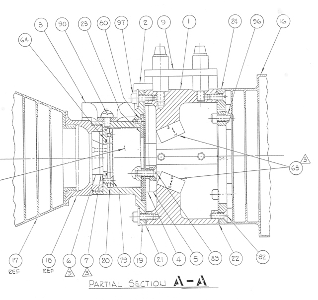
Figure 4.3b LAN2B telescope assembly WART cross section detail. Rotated 15° CW, scale=2:1
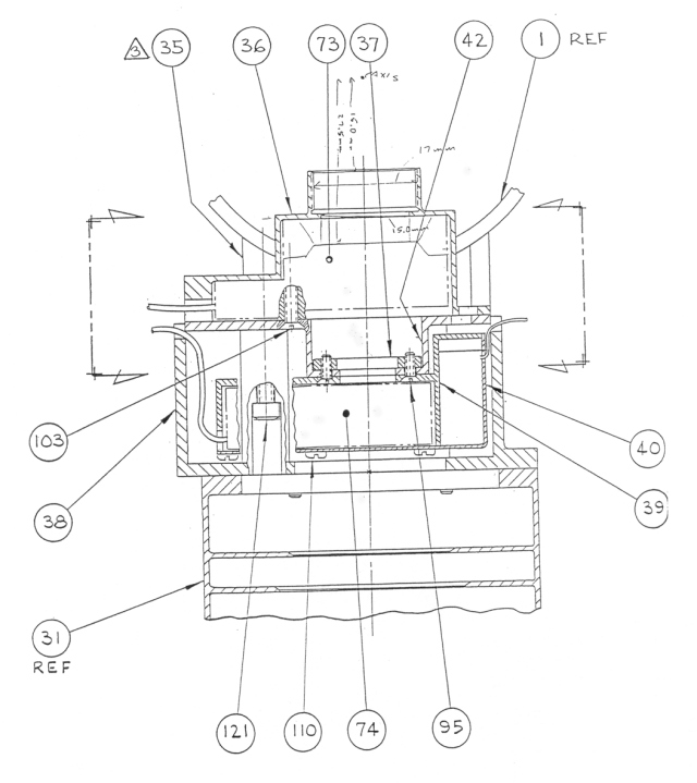
Figure 4.3c LAN2B assembly MF cross section detail
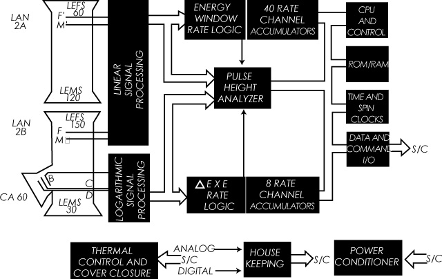
The pulse-height-analyzer system is also used to obtain 32 channel energy spectra (referred to as MFSA) of the singles rates in the LEMS and LEFS telescopes. The singles rates in the individual detectors are monitored and telemetered in a multiplexed mode. These rates are used as engineering monitors of the instrument performance and can also be used, if required, to make pulse-pileup corrections to the coincidence rates. Figure 4.3d shows how the principal features of the HISCALE system interact.
Figure 4.3d LAN2B telescope assembly, exterior view MF-WART
Next: Chapter 4.2: Mechanical Features
Return to Chapter 4 Table of Contents
Return to Ulysses HISCALE Data Analysis Handbook Table of Contents
Updated 8/8/19, Cameron Crane
QUICK FACTS
Mission End Date: June 30, 2009
Destination: The inner heliosphere of the sun away from the ecliptic plane
Orbit: Elliptical orbit transversing the polar regions of the sun outside of the ecliptic plane