


Ulysses HISCALE Data Analysis Handbook
4.14 Calculation of Geometric Factors Including the Effect of Vignetting
Document Source: Dr. Ed Roelof
Date: Feb. 29, 1992
I have re-calculated the geometric factors for all heads (except the deflected electrons DE1-4). Rob Gold, Ray Thompson, and I went through copies of the original APL and Berkeley engineering drawings to estimate the relevant dimensions. The new factors differ from those given in IDF.DAT, particularly for the 2-parameter measurements with the WART composition aperture (which is now reduced by a factor of 2.4). The smaller differences for the other heads are the result of a more accurate calculation of the vignetting within the head.
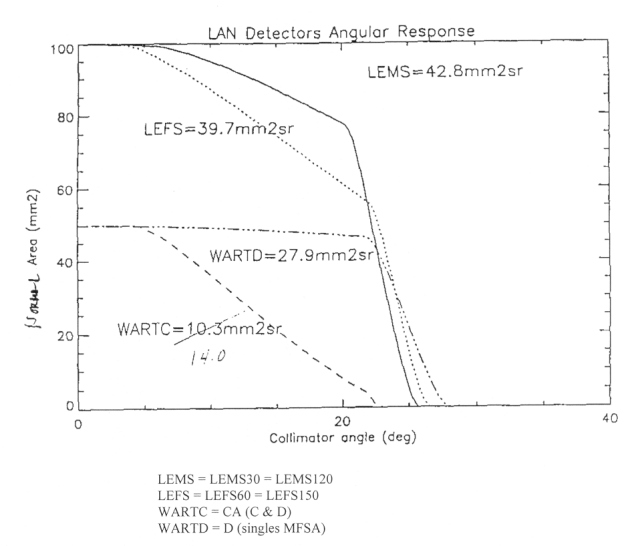
I am preparing a memo which describes the calculation and gives plots of the angular responses, i.e., the detector normal area as a function of the incident angle with respect to the collimator axis.
These values should NOT yet be considered definitive, as we are still double-checking the measurements. When Rob and I are satisfied that we have made the best possible estimates, Rob will issue a revised version of IDF.DAT. I’m giving you the current estimates to alert you that the old numbers are likely to change. Units are cm2sr.
| IDF.DAT (1/14/92) | Re-Calculation (2/29/92) | |
| LEMS30/120 | 0.48 | 0.428 |
| LEFS60/150 | 0.48 | 0.397 |
| WART (CA 2-param) | 0.24 | 0.103 |
| WART (singles) | 0.30 | 0.279 |
Note that LEFS is no longer equal to LEFS. James Tappin and I had noticed a discrepancy that James included in MOVIE as a “foil factor.” As James states in Section 4.10 of his IDL manual:
“This factor is necessary as even a cursory inspection of a movie for a relatively isotropic period shows that the geometry factor of the foil detectors is less than that of the magnetic ones. The appropriate value appears to be about 1.25. But this does depend on the channels.”
Looking at the recalculated values, the foil factor is estimated to be .428/.397 = 1.08. This is not as large as James suggests, but it goes in the right direction. Also, it should be the same for all channels. Consequently, the new numbers don’t completely resolve the apparent “foil-factor” discrepancy, but we seem to be down to about a 15% residual effect.
Figure 4.89 LAN detectors angular response
FROM: James Tappin
Date: March 5, 1992
When you are putting the new geometry factors into IDF.DAT can you also note the following corrections:
W8 E-Hi - 15000 (surely not 150000)
P1 E-Hi and P2 E-Lo - I’m not sure what this should be but certainly not 82 (65 perhaps).
On foil factors, I suspect that the small differences in energy limits between the detectors may contribute to the “missing 15%” - it’s in the right sense but I haven’t checked whether the magnitudes are okay.
Next: 4.15 RTG Radiation Background Tests
Return to Chapter 4 Table of Contents
Return to Ulysses HISCALE Data Analysis Handbook Table of Contents
Updated 8/8/19, Cameron Crane
QUICK FACTS
Mission End Date: June 30, 2009
Destination: The inner heliosphere of the sun away from the ecliptic plane
Orbit: Elliptical orbit transversing the polar regions of the sun outside of the ecliptic plane