


Ulysses HISCALE Data Analysis Handbook
4.2.1 Compilation of Useful Mechanical Diagrams and Instruments
Figure 4.4 HISCALE instrument assembly photograph
Figure 4.4a LAN assembly field of view drawing
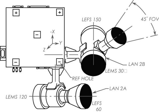
Figure 4.4b HISCALE assembly FOV drawing, detail a
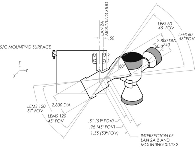
Figure 4.4c HISCALE assembly FOV drawing, detail b
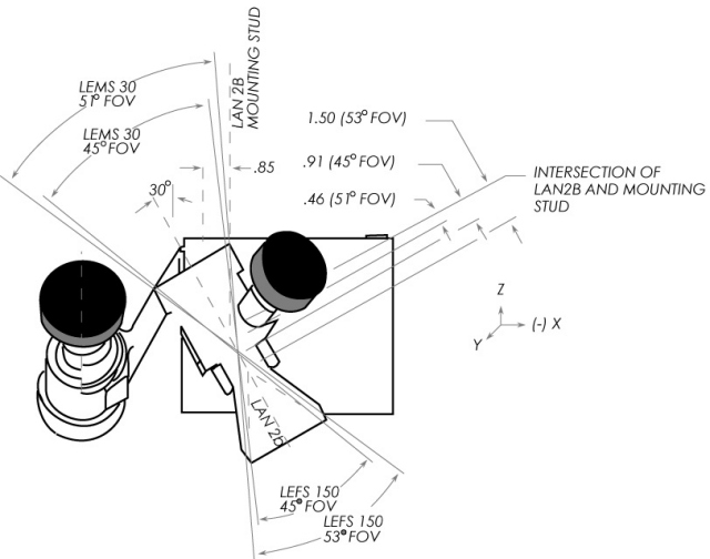
Table 4.1 HISCALE assembly FOV calculation summary
| 1. Field of view location with respect to the reference hole | |||
| FOV | x cm | y cm | z cm |
| LEMS 30 51° | -2.75 | 10.50 | -9.00 |
| LEFS 150 53° | -4.09 | 10.50 | -11.25 |
| LEMS 120 51° | 0.50 | -0.12 | -10.39 |
| LEFS 60 53° | 0.50 | 2.15 | -9.07 |
| LEFS 60 45° | 0.50 | 0.84 | -9.80 |
| LEMS 30 45° | -3.33 | 10.50 | -10.06 |
| CD 45° | -4.15 | 14.07 | -6.42 |
| 2. Reflected light avoidance cone (80°) location with respect to the reference hole: | |||
| LEMS 30 | -1.16 | 10.50 | -6.30 |
| LEMS 120 | 0.50 | 3.64 | -12.56 |
| CD | -5.40 | 6.00 | -4.03 |
| CD angles to S/C axes: | x | y | z |
| 110.39 | 37.54 | 60.0 | |
| Polar angle of CD=60° | |||
| Clock angle in spin plane from x axis toward y axis = 48.60° | |||
Figure 4.4d Outline flight model LAN experiment, detail 1
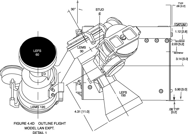
Figure 4.4e Outline flight model LAN experiment, detail 2.
Click here for a larger view (PDF file).
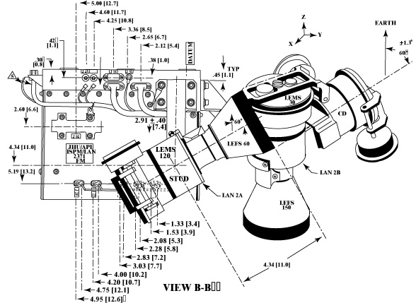
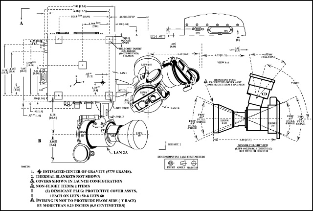
Figure 4.4f Outline of
flight model LAN experiment.
Document reference: APL Document 7256-2010.
Click here for
a larger view (pdf file).
Return to Chapter 4 Table of Contents
Return to Ulysses HISCALE Data Analysis Handbook Table of Contents
Updated 8/8/19, Cameron Crane
QUICK FACTS
Mission End Date: June 30, 2009
Destination: The inner heliosphere of the sun away from the ecliptic plane
Orbit: Elliptical orbit transversing the polar regions of the sun outside of the ecliptic plane