


Ulysses HISCALE Data Analysis Handbook
The following is a reproduction of a letter from Mr. Robert D. Campbell at UC-Berkeley to Dr. Rob Gold at APL, originally produced on January 12, 1984.
Dr. R. Gold
Applied Physics Laboratory
Johns Hopkins University
Johns Hopkins Rd.
Laurel, MD 20707
Dear Dr. Gold,
Enclosed are seven foils originally received July 1983, four foils received January 1984, the certification for the latest foils and a description of the fabrication techniques for both lots.
A visual inspection of one side revealed no changes on the July 1983 lot. Two foils were probably mislabeled at Luxell in the latest lot ("flight" #9 has a stain; 'test'-stain does not).
We are retaining one foil from each lot for further testing.
Sincerely,
Robert D. Campbell
Space Sciences Laboratory
Berkeley, California 94720
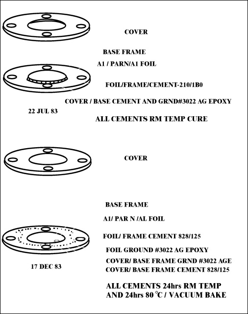
Document Reference: Luxel Corporation document prepared by G. Steel, 17 Dec. 1983
Filter Certification
5 AMPTE filters, dated 17 Dec. 83; 3 flight grd., 2 eng. grd.
Filter No.: None; Foil Structure: Al/Paryl N/Al
Film:
| Run No. | Date | Material | Lot No. | Thickness +/- Tol. |
| 01947A | 20 Jun | Al 5N | 13/76013 MRC |
4760 +/- 100 Å |
| UCC | 13 Jul | Parylene N | 2.35 +/- 0.1 Åm | |
| 01947B | 14 Jul | Al 5N | same | 3980 +/- Å |
Mesh: None
| Frame: | Type/Matl. - Alum/Iridite |
| Clean/Bake - Ultrason/Acetone-Bake | |
| By: GS | |
| Frame/Foil - 828/125 | |
| Cement - Epoxy | |
| Date - 14 Dec. | |
| Lot No. - 8EHJ35/3A8012 | |
| Expr. Date - Oct. 84 | |
| By: GS |
Post Fabrication Treatment: Vacuum bake, 24 hrs., temp. 80º C, by GS
Inspection: Visible light transmission - all < 1 x 10⁻⁹; date 17 Dec., by GS
Notes:
*Foil grounded to frame and cover frame grounded.
+To base frame with Acme E solder 3022, lot # 9650 (XPR Oct
84)
Parylene Thin Films for Radiation Applications (document Source: M.A. Spivack).
Thin films are used in various aspects of radiation detection. In gas filled ionization detectors for soft and ultrasoft x-rays, windows are required which are transparent in this spectral region and yet can act as a gas barrier. Other uses include radioactive source backings, nuclear radiation absorbers, accelerator targets, and supports for 4-pi counters.
Various materials have been used including Mylar films 6.3 and 3.8 m thick, 2 m thick polycarbonate, and 12.7 m thick polypropylene, all commercially available. For thinner films, resins such as VYNS, Formvar, and collodion can be cast from a suitable solvent, and polypropylene is stretchable down to 1 m. Thin metal foils and other polymers and oxides have also been used. Each of the above shows deficiencies in one or more areas. For example, the film may be too opaque to low energy radiation, a poor gas barrier, non-uniform in thickness, contain pinholes, contain impurities such as plasticizers and mold release agents, have poor thermal resistance, and/or have poor resistance to acids, bases, and solvents. This paper describes the preparation and characterization of thin films fabricated from polymers based in the above areas.
Parylene is the generic name of a family of polymers based on poly-p-xylylene. Unsupported membranes of parylene were prepared by using the vapor phase deposition process as described by Gorham. By this method, di-p-xylylene is heated to the gas phase in vacuum, quantitatively cleaved to a diradical species, and subsequently deposited as a polymer directly from the gas phase.
The substrates used were glass plates, treated with a parting agent such as a vacuum evaporated alkali halide. After deposition of the polymer to the desired thickness, a suitable mount is attached to the polymer coated glass and the parting agent is then activated by solution in water. Free films, several cms. in diameter, have been prepared as thin as 0.018 m by this method.
The films thus formed have excellent mechanical, physical, electrical, and barrier properties. They are virtually inert to most acids and bases and are insoluble in most organic solvents below ~170º C. In oxygen-free environments, parylene can be used for brief periods in excess of 350º C and for extended periods in excess of 220º C. At atmospheric conditions, however, parylene will embrittle at these conditions, and the extended use temperature is limited to about 100º C. The good thermal stability in vacuum is reflected in the ability to vacuum metallize free standing parylene thin films to, for example, make them conductive or light tight. The polymers also exhibit excellent vacuum stability to high intensity ionizing radiation.
Because of the pressures at which the deposition is conducted (50-200 mTorr), the deposition is not line-of-sight and there is little difficulty in obtaining good uniformity. Several 2.5 cm diameter samples were lifted from random portions of the substrates contained within the deposition chamber. The total surface area sampled was ~1500 cm2. The thickness by interference fringes at all thickness levels varied by about + 1.5%.
In order for a thin film to act as a window in either a sealed or flow proportional counter, it must have the ability to separate two ambients, e.g., counting gas from atmosphere or vacuum. One criterion of this ability is the inherent gas permeability diffusion pathways (viz., pinholes).
Table 4.3 lists the permeability constants for several commonly used window materials along with those of the two commercially available parylenes. Parylene C is about equivalent in permeability to Mylar, the only difference being that parylene C is a better moisture barrier.
Table 4.3 Properties of Commmercial Window Materials
| Film Material |
Commercial Name | Emperical Formula | Min. thickness μ | Density (g/cm3) | O2 | N2 | He | H2 | CO2 | H2O |
| Poly-(choro-p-xylene) | Parylene C | C6H7Cl | 0.025 | 1.289 | 0.03 | 0.0036 | 0.99 | 0.66 | 0.046 | 20 |
| (Poly-p-xylene | Parylene N | C6H8 | 0.025 | 1.11 | 0.34 | 0.047 | 2.5 | 3.2 | 1.3 | 57 |
| Polyethylene terepthalate | Mylar | C10H8O4 | 3.8 | 1.397 | 0.22 | 0.0049 | 1.1 | 0.42 | 0.096 | 60 |
| Polypropylene | Udel film | C3H6 | 12.7 | 0.905 | 0.9 | 0.18 | 5.6 | 4.9 | 3.0 | 39 |
| Polycarbonate | Kinfoil | C16H14O2 | 2.0 | 1.20 | 1.5 | 0.26 | c | 9.6 | c | 370 |
| Poly (vinyl chloride) | VYNS | 90%C2H3Cl | b | 1.39 | 0.1 | 0.05 | c | 2.1 | 0.27 | 210 |
| Poly (vinyl acetate) | 10%C4H6O2 | |||||||||
| Poly (vinyl formal) | Formvar | 82%C5H8O2 | b | 1.23 | 0.24 | 0.018 | 1.6 | 0.93 | c | 575 |
| Poly (vinyl acetate) | 12%C4H6O2 | |||||||||
| Poly (vinyl alcohol) | 6%C4H2O |
Poly-propylene and polycarbonate are particularly poor in regard to their ability to act as barriers to hydrogen and helium. VYNS, polycarbonate and Formvar are poorer water vapor membranes than the other materials.
The high water permeability of Formvar is reflected in its high water absorption (~8% in comparison with values of < 0.1% for most of the other materials.) This high absorption can adversely affect the other permeability values. For example, the dry oxygen permeability value of Formvar (Table 4.3) is 0.024 x 10⁻¹⁰ cm-3 (STP) cm/cm2.sec.cm Hg. Increasing the relative humidity to 50 and 100% increases the oxygen permeability by an order of magnitude to 0.19 x 10⁻¹⁰ and 0.28 x 10⁻¹⁰ cm3 (STP) cm/cm2.sec.cm Hg, respectively.
The permeability values of Table 4.3 were obtained on relatively thick films (25-75 m). If thin films are to act as gas barriers, not only must the criterion of low permeability be met but the thin film must also be structurally continuous. Previous work by this author with water vapor has shown that parylene C membranes are pinhole free at least down to thicknesses of 0.030 m.
The radiation transmission of a material can be calculated from the weighted summation of the mass absorption coefficients of the elements. Using the mass absorption coefficients (m/p) measured or calculated by Henke et al., Victoreen, and Allen and the densities (r) listed in Table 4.3, the mass absorption per unit thickness may be calculated. The values are shown in Table 4.4 for the wavelength region 10 80 Å (1.24-0.55 keV). Table 4.4 can be construed as the ln(Ia/I) for a 1 m thick film (I/Iu being the fraction of radiation transmitted through a given film thickness). Comparing the various polymers at this equal thickness level, it is observed that polypropylene, due to its low thickness level, its low density and the absence of absorbing elements other than carbon, is the most transparent material within this spectral region. Below the K absorption edge of oxygen, polypropylene is followed in transparency by parylene N, parylene C, polycarbonate, Formvar, VYNS, and Mylar, the latter being the most opaque. Between the K absorption edge, parylene N and polypropylene are more transparent than the other materials.
The above is based on the assumption that all the materials listed are available or can be produced in thicknesses of 1 m. As listed in Table 4.3, the thinnest Mylar available is ~3.8 m and the thinnest commercial polypropylene is ~12.7 m. Polycarbonate can be purchased as 2.0 m films; VYNS and Formvar are sold commercially in resin or solution form. Parylenes N and C are available as thin as 0.025 m. Sinha and Bhattacharyya report that ~1.5 m Mylar can be made; Caruso and Kim have stretched polypropylene to ~1.0 m, and VYNS can be made as thin as 0.007 m. Capacitance measurements on parylene film as thin as 0.004 m have been observed.
Using the absorption coefficients of Table 4.4, the percent transmission of commercially available films of Mylar, polypropylene, parylene N, parylene C and polycarbonate can be calculated. The 1.0 m thick polypropylene of Caruso and Kim is also included here for comparison. At an energy of 1 keV, 0.1 m thick parylene will absorb less than 2% of the incident radiation, 2.0 m thick polycarbonate about 43% and 3.8 m thick Mylar about 76%. At 0.5 keV, the parylenes are ~86% transmittant, and polycarbonate ~9%; Mylar is virtually opaque. At 0.2 keV, 0.1 m parylene N will pass ~95% of the incident energy which is about 50% more than stretched polypropylene, about five times as much as 2.0 m polycarbonate and nearly 60 times that of the thinnest available Mylar.
Table 4.4 Unit mass absorptions of various window materials
| 1(A) | Parylene N | Parylene C | Polypropylene | Polycarbonate | Mylar | VYNS | Formvar |
| 10 | 0.117 | 0.157 | 0.088 | 0.164 | 0.223 | 0.200 | 0.190 |
| 15 | 0.356 | 0.449 | 0.269 | 0.472 | 0.627 | 0.540 | 0.533 |
| 20 | 0.784 | 0.975 | 0.593 | 1,030 | 1.357 | 1.154 | 1.156 |
|
K absorption edge of oxygen at 1=23.301 L |
|||||||
| 25 | 1.363 | 1.697 | 1.032 | 1.237 | 1.224 | 1.844 | 1.027 |
| 30 | 2.080 | 2.580 | 1.574 | 1.890 | 1.872 | 2.794 | 1.569 |
| 35 | 3.094 | 3.733 | 2.342 | 2.799 | 2.271 | 3.936 | 2.335 |
| 40 | 4.457 | 5.220 | 3.374 | 4.043 | 3.997 | 5.341 | 3.350 |
|
K absorption edge of carbon at 1=43.648 L |
|||||||
| 45 | 0.249 | 1.869 | 0.189 | 0.351 | 0.480 | 3.637 | 0.4009 |
| 50 | 0.326 | 1.976 | 0.247 | 0.460 | 0.629 | 3.776 | 0.536 |
|
L1 absorption edge of chlorine at l=52.084 L |
|||||||
| 55 | 0.410 | 2.304 | 0.310 | 0.584 | 0.803 | 4.373 | 0.684 |
| 60 | 0.500 | 2.611 | 0.379 | 0.722 | 0.999 | 4.866 | 0.851 |
|
LII and LIII absorption edges of chlorine at 1=61.366 Å and 1=61.672 Å, resp. |
|||||||
| 65 | 0.600 | b | 0.455 | 0.786 | 1.220 | b | 1.039 |
| 70 | 0.712 | b | 0.539 | 1.046 | 1.459 | b | 1.242 |
| 75 | 0.842 | b | 0.638 | 1.229 | 1.710 | b | 1.458 |
| 80 | 0.984 | b | 0.745 | 1.415 | 1.956 | b | 1.668 |
In conclusion, the combination of extremely good thickness uniformity, good inherent barrier properties, absence of pinholes, and very high radiation transmission in the soft and ultrasoft x-ray region point to the parylenes as attractive materials for radiation detection applications.
The author of this section on films, M.A. Spivack, would like to thank Ted Zehnpfennig of Visidyne Corporation for his advice and Dr. Lloyd Robeson of this laboratory for the gas permeability measurements:
1. G. Brown and R. Kanaris-Sotiriou, J. Sci. Instrum.
Scr. 2,2,551 (1969)
2. B.K. Sinha and R. Bhattacharyya, Nucl. Instruments
Methods 64, 107 (1968)
3. M.A. Volkar and R.L. Wolke, Rev. Sci. Instrum. 40, 849
(1969)
4. B.D. Plate and L. Yaffe, Can. J. Chem. 33,15 (1955)
5. W.L. Baun, Rev. Sci. Instrum. 40, 1101 (1969)
6. M.A. Spivack and G. Ferrante, J. Electrochem. Soc. 116,
1592 (1969)
7. J.A. Victoreen, J. Appl. Phys. 20, 1141 (1949)
8. S.J.M. Allen, Handbook of Chemistry and Physics, 44th
Ed., p. 2766
9. B.L. Henke, R. White, and B. Lundberg, J. Appl. Phys. 28,
98 (1957)
Figure 4.24 Foil Mount.
Document Reference: Drawing. no. 600-A-1025, Rev. B,
5/26/83, RHW, Space Sciences Laboratory, Univ. of
California-Berkeley.
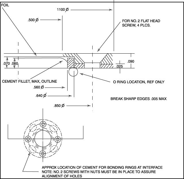
Unless otherwise specified, dimensions are in
inches.
Tolerances are: decimals: .xxx +/- .005; angles: +/-
1/2°
Material: Alum. 6061-T6; finish: black anodize
Next: Chapter 4.3: Analog Electronics
Return to Chapter 4 Table of Contents
Return to Ulysses HISCALE Data Analysis Handbook Table of Contents
Updated 8/8/19, Cameron Crane
QUICK FACTS
Mission End Date: June 30, 2009
Destination: The inner heliosphere of the sun away from the ecliptic plane
Orbit: Elliptical orbit transversing the polar regions of the sun outside of the ecliptic plane