


Ulysses HISCALE Data Analysis Handbook
The detector signals are fed to charge-sensitive preamplifiers, linear shaping amplifiers, and then to discriminators. The analog electronics are largely of hybrid construction. In addition to the preamplifier, amplifier, and discriminator circuits, these hybrids include logarithmic amplifiers, accumulators, one-shots, peak detectors, power controllers and modules required for the pulse-height-analyzer system.
The HISCALE log amplifiers, used in the CA system and with the pulse-height-analyzed F and M detectors, provide an accurate logarithmic response over a >103 dynamic range, with usable calibration curves over a >104 range. The design uses temperature compensation by heaters to ensure accurate performance throughout the mission.
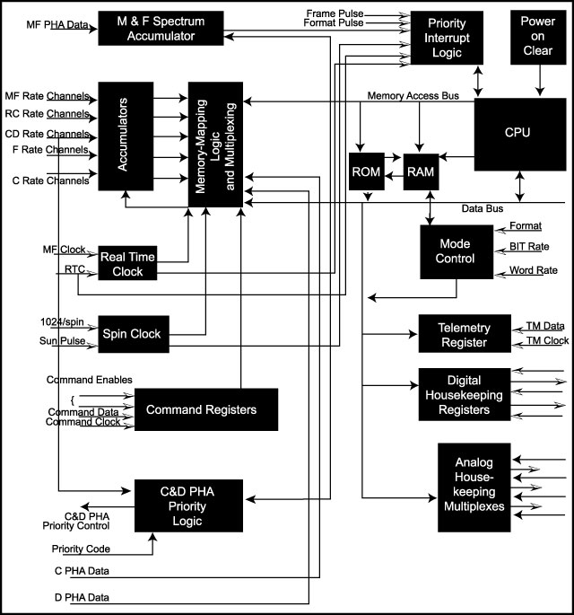
The rate logic (used to define the energy channels in Tables 1.1-1.2) employs relatively simple, single-detector, differential energy windows. The composition rate channels use slanted discriminators (Figure 4.32) to define the species group channels defined in Table 1.3. Figure 4.25 shows the HISCALE signal flow in block diagram flow.
Appendix 17 contains the engineering memos which report on analog electronic bench testing.
Figure 4.25 HISCALE digital signal block diagram
Return to Chapter 4 Table of Contents
Return to Ulysses HISCALE Data Analysis Handbook Table of Contents
Updated 8/8/19, Cameron Crane
QUICK FACTS
Mission End Date: June 30, 2009
Destination: The inner heliosphere of the sun away from the ecliptic plane
Orbit: Elliptical orbit transversing the polar regions of the sun outside of the ecliptic plane