


Ulysses HISCALE Data Analysis Handbook
The basic timing sequence of the data system is as follows: Data is accumulated, stored, and processed over various numbers of spins and sectors, and output a short time later to the S/C telemetry channel. This simple scenario is complicated by many factors. There are four S/C telemetry modes, implying four bit rates for each telemetry mode. In addition, the telemetry mode can change at the beginning of any S/C format, not necessarily at the beginning of the LAN Data format. An example is shown in Figure 4.45.
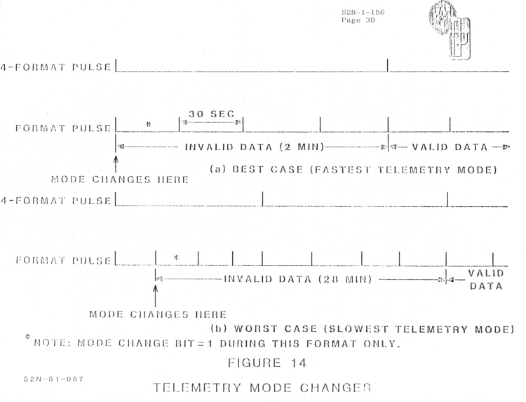
Figure 4.45 Telemetry mode changes
The input timing sequence is also complex. The range of and transitions in spin rate must be accounted for. The experiment provides information about the spatial origin of events by treating each spin as eight sectors of approximately equal duration. Two sectoring modes are provided. During sun sectoring, each spin is defined as starting some fractional spin after the sun-S/C meridian is passed. The duration of each sector is defined by a fixed count of a clock derived from the previous two detections of the sun crossing. When the period between sun crossings (the spin rate) is outside some fixed limits, the time sectoring mode is active. A pseudo-sector of commendable duration is created, and accumulations then occur over this new period. The experiment may be commanded to either use only time sectoring or to automatically switch between time sectoring and sun sectoring based on spin duration. This prevents processing data which is generated too quickly for accurate sampling, due to delays of program execution time, or too slowly to fit the data format. During times of minor spin rate variation, we attempt to maintain nearly constant the lag between the occurrence of the sun pulse and the beginning of the first sector, as well as the duration of each sector. The lag between the sun-S/C meridian crossing and the beginning of a spin is also commendable. The lag minimizes the number of sectors for which data is strongly affected by the sun. Timing delays, variations in spin rate, and sectoring modes for each spin group are telemetered in the status trailer of the data stream and in the digital housekeeping (DHK) stream. This section describes the input and output timing sequences. In general, the process for the fastest telemetry mode is described, and then details for slower modes are defined.
Initialization. The data system maintains a set of pointers which are moved through the output data queue addresses as each frame of data is output. These pointers are initialized at power-up and at the occurrence of the four-format pulse. Since power-up is assumed to be independent of telemetry timing, the output data is skewed until the first subsequent occurrence of the four format pulse. Digital housekeeping data and the analog housekeeping channel assignments are also invalid until the four format pulse occurs. Note that although the digital science and housekeeping output channels are then synchronized, data is not yet valid. The relationship within the queue of the input pointers to the output pointers will not be guaranteed correct until the next data collection cycle starts.
So analog housekeeping data becomes valid upon the first four-format pulse occurrence after power-up, and digital science and housekeeping data become valid upon the second four-format pulse occurrence after power-up.
Telemetry Mode Changes. Changes of the S/C telemetry mode do not cause frames or formats to be dropped, so the output pointers are not affected. However, the input sequence becomes completely meaningless, so the synchronization procedure must occur again. Therefore, after the mode changes, data is invalid until the second subsequent occurrences of the four-format pulse (counting any which occurred at the same time as the mode change; Figure 4.46 shows two potential sequences of events and the corresponding status of data validity.) When the mode changes, the mode change bit is set and appears immediately afterward in the status preamble. This bit is reset at the next occurrence of the format pulse, so it appears only once for each change of mode. The mode ID bits, however, are telemetered for each format of data.
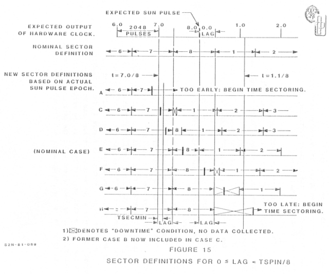
Figure 4.46 Sector definitions for 0<=LAG<TSPIN/8
Slow Telemetry Modes. The output format is identical to Figures 4.35-4.37 regardless of S/C telemetry mode; only the interval over which data is accumulated changes.
Definitions. A spin group consists of 1, 2, 4, or 8 consecutive spins, depending on the S/C telemetry mode: 1 spin during the fastest mode and 8 spins during the slowest.
A data collection cycle, or cycle, consists of 10 consecutive spin groups and, therefore, 10, 20, 40, or 80 spins. There is a one-to-one correspondence between data collected during a cycle and data output during a four-format, with minor exceptions.
Cycle Starting Slot. A data queue is used, rather than saving data for an entire input cycle, in order to minimize the memory requirements. Therefore, some minimum delay is required between inputting and outputting data. The delay is ensured by starting the data input cycle within a fixed window in time prior to the S/C 4-format pulse. Computer simulations of the input and output process were run under conditions of varying spin rate to determine the minimum delay and maximum data buffer required. It was determined that the starting window should extend from 1-3/4 to 3/4 maximum spin group durations prior to the four format pulse.
Skipped Spins. When the spin rate is faster than the slowest allowable rate, the time required to input data for 10 spin groups will be less than the 4-format period. The end of the data collection cycle will slip backward in time relative to the cycle starting slot, and eventually will end prior to the cycle starting slot. When this happens, spins will be skipped for data collection purposes until one ends within the cycle starting slot. Note that spins, not spin groups, will be skipped. This feature allows sampling during the full desired spin count, particularly after initialization, and helps avoid dropped spins.
Dropped Spins. At times it will be necessary to drop spins from the end of the data collection process; that is, to collect data over a number of spins less than 10 x 2n. This situation may occur during initialization or when the S/C spin rate is very close to either limit of the allowable rates for sun sectoring. The final spin count for each collection cycle is telemetered in the status trailer and allows for a count of fifteen less than the expected number.
Cycle Start. Under conditions similar to those causing dropped spins, it will be necessary to start the data cycle with the second spin group rather than the first. This condition is also telemetered in the status trailer. Note that the status trailer telltales the conditions which have most recently occurred, which are the end of cycle M and the start of cycle M+1.
Data Validity. If spins have been dropped, the rate and CA data for those spins are invalid. The rate common to a spin group which has lost some spins must be multiplied accordingly. The interval of MFSA data collection may or may not have been shortened; this cannot be determined. If the cycle started with spin group 2, the rate and CA data for group 1 and the rate data common to groups 1 and 2 are invalid. The MFSA data is then accumulated over the duration of 9 spin groups rather than 10.
Changes in S/C Spin Rate. When using the sun sectoring mode the data system relays the origin of events to the angle relative to the sun line. During time sectoring, the pseudo-sectors generated can be related to the four format pulse, and their duration is commendable. In either event, the S/C will time-tag epochs of the magnetic field zero-crossing, and ground programming will attempt to relate the magnetic field to the origin of events.
The steady state spin period of the S/C is nominally 11.76 to 12.24 seconds; there will also be periodic transient effects. A requirement was derived for the data system to accommodate a range of 11.17 to 12.275 seconds while using sun sectoring, and to use time sectoring if the period falls outside of that range. The data system can also be commanded to maintain time sectoring regardless of spin period. This feature would be used in the event of failure or erratic operation of the S/C sun sensor. The sectoring mode may change at any time as long as auto sectoring is enabled.
Telemetering Sector Mode Changes. The sectoring mode used for each spin group is telemetered in bytes 17 and 18 of the status trailer. These bits are set at the end of the first spin of each group. Therefore, any mode change first appears for the next group. During the fastest telemetry mode, the contents of trailer byte 17 being (0011 1111) indicted that spin groups 1 and 2 (of 1 to 10) used sun sectoring and groups 3 through 8 used time sectoring. During slower telemetry modes, the same contents indicate the same result for groups 1 and 3 through 8; however, group 2 may consist entirely of sun sectored spins, and the corresponding data validity bit in byte 15 of the trailer will be zero; otherwise it will be a one. Similar statements apply to sectoring mode changes from time to sun. Even if the validity bit is zero, the last spin of the group prior to the mode change may have been truncated at an unknown time, and data for that prior group is invalid.
Time Sectoring. When time sectoring is used, sectors are defined as count of the high frequency clock. The duration of these sectors then varies only by command. This duration can take on values ranging from 1.414 to 1.589 seconds in 0.017 second increments (spin periods from 11.286 to 12.714 seconds in 0.413 second increments). It is necessary to specify a time sector duration each time automatic mode switching is enabled or disabled.
Time sectoring spins are generated independently of all epochs except the cycle starting slot, but can be related to the four format pulse.
Sun Sectoring. When sun sectoring is used, a spin is defined as starting some commendable interval after the sun pulse epoch. Each sector thereafter normally lasts the duration of 2048 counts of the 16384 x Spin Clock. The S/C adjusts the rate of the 16384 x Spin Clock at each sun pulse epoch based on the interval since the previous epoch, so the 16384 x Spin Clock rate lags the spin rate by one spin at all times. During times of varying spin rate the sun pulse can therefore occur more or fewer than 16384 counts after the previous epoch.
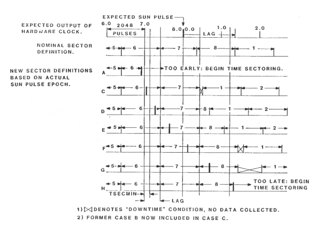
Timing Requirements. Based on the above scenario, two requirements were derived for data system operation during sun sectoring. The lag from the sun pulse epoch to the start of a new spin is to be maintained constant in terms of counts of the (varying) 16384 x spin clock. Also, the duration of each sector is to be maintained constant as far as possible. Timing conditions relating desired sector boundaries to the expected and the actual sun pulse epoch are shown in Figure 4.46 for a commendable lag of less than one sector duration, and in figure 4.47 for a lag of more than one but less than two sector durations. At each sun pulse or sector end epoch, the data measures the time relative to the previous sun pulse epoch and adjusts the state of internal flags to provide for future timing operations.
Figure 4.47 Sector definitions for TSpin/8<=Lag<TSpin/4
Telemetering Changes in Spin Rate. A decrease in spin rate can cause truncation or elimination of sector 8. In order to properly process the counts for each sector and relate them to the orientation of the S/C, the changes in spin rate are telemetered in the digital housekeeping channels.
Telemetering Delays in Sector Flag Processing. Short delays may infrequently occur between a sector flag epoch and processing data for that sector. These delays are telemetered in the status trailer.
Interpretation of Data Validity
When a change of sectoring mode is indicated in the status trailer, rate and CA data from the last spin group under the old mode is invalid. CA data is valid during the previous and the next spin group. If the new mode starts with an odd spin group, all of the rate data for the new group is valid, and that rate data which is summed over two spin group intervals (labeled 'C' & 'D' and 'S' in the flowcharts) for the previous spin group is invalid. If the new mode starts with an even spin group, that rate data summed over only one spin group interval ('A & B') is valid for the new group, and the C & D and S data for the spin group pair is valid but was summed during one spin group only.
In the fastest telemetry mode, the data validity bits in the status trailer should always be zeroes (valid). The presence of 0's does not impugn the conditions for validity presented in the previous paragraph while in any telemetry mode. However, in the slower telemetry modes it is possible for changes of sectoring mode to occur for individual spins but not show up in the status trailer. In this case, the data validity bit is set to 1 for the spin group during which the change(s) occurred. Rate and CA data are invalid for that spin group. (A datum is valid during the previous and the next groups. If the validity bit set during an even odd spin, the A & B data for the subsequent (even) spin is valid, and the C & D data for the spin group pair is valid but was summed over one spin group only.
Invalid MFSA data is not generated. If a sectoring mode change occurs, any or all of the four MFSA data groups may have been summed over fewer sectors than normal. As these summations are performed on entire data groups, the counts within a group are relatively correct.
The eighth sector of a spin may be truncated or dropped. Any value in the DHK stream other than OO of FF indicates a truncated eighth sector. In slower telemetry modes, this is detected only if it occurs during the last spin of a group. The eighth sector was dropped completely if the value of SPX, X = 1 to 10, is less than 90 and the value of LAG (Commendable, telemetered in the status preamble) is greater than 1/8 sector.
In some cases, blocks of invalid rate data are zeroed as an aid for detecting invalid data. Not all invalid data is zeroed; the tests described above must be applied.
Next: Chapter 4.5.16: Commands
Return to Chapter 4 Table of Contents
Return to Ulysses HISCALE Data Analysis Handbook Table of Contents
Updated 8/8/19, Cameron Crane
QUICK FACTS
Mission End Date: June 30, 2009
Destination: The inner heliosphere of the sun away from the ecliptic plane
Orbit: Elliptical orbit transversing the polar regions of the sun outside of the ecliptic plane