


Ulysses HISCALE Data Analysis Handbook
The science data format consists of 2560 bytes of four data types as shown in Figure 4.35. The numbers in parentheses are byte counts for each block of data, each byte being eight bits. Whenever blocks of data are shown or listed, the topmost bit or byte is output first; the leftmost bit is the MSB.
Two types of science data are shown. The MFSA data originates from the M&F channel Spectrum Accumulator. This data is collected for a specified particle type, during selected sectors, for the entire cycle.
The MFSA assigns each event to one of 32 counting bins, and the 32 bins of data are summed into one of four groups determined by the rotational sector, so 128 values are output. Rate data from 48 rate accumulators and CA data from the Composition Aperture Pulse Height Analyzer form the second type of science data. Rate data is summed, and CA data is sorted by event priority, over individual sector. Some rate channels must be summed over two sectors and some over two spins. During slower telemetry modes, rate and CA date are processed over multiple spin periods, or spin groups. For example, during the slowest telemetry mode, the rate shown in Figure 4.35 and subsequently as originating during spin 1 would actually represent data summed during spins 1-8, which will be labeled "spin group 1;" spin 2 would represent spins 9-16, or "spin group 2," and so on.
The two remaining data types, the status preamble and the status trailer, specify data types, commendable parameter states, and timing conditions to increase the accuracy of data analysis.
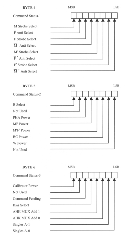
Status Preamble. Bit definitions for the status preamble are shown in Figures 4.39 and 4.40.
Figure 4.39 Status preamble definitions, bytes 1-3
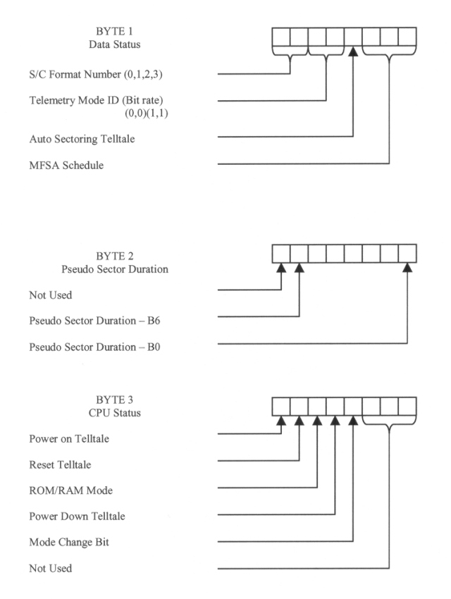
Figure 4.40 Status preamble definitions, bytes 4-6
Format Number. The format number will range from 00 (first format) to 11 (fourth format). The first format begins immediately after the occurrence of the four-format pulse.
Mode ID. The telemetry mode ID is the state generated by the S/C. The MSB represents Line 2; the LSB represents Line 1. It is sampled immediately after the format pulse.
Auto Sectoring Telltale. The auto sectoring telltale will be a one when the sectoring mode may switch between time and sun sectoring. It will be a zero when only time sectoring is allowed.
MFSA Schedule. The MFSA schedule bits define the detector and sectors used to collect MFSA according to a preset schedule. Note that these lines refer to the schedule currently in use; the data contained in the first format was collected during the previous cycle and used the previous MFSA schedule.
SECTORS COMPOSING DATA GROUP
| Schedule | MSB LSB | Detectors | A | B | C | D |
| 1 | 000 | M | 1,2 | 3,4 | 5,6 | 7,8 |
| 2 | 001 | F' | 1 | 3 | 5 | 7 |
| 3 | 010 | M' | 1 | 3 | 5 | 7 |
| 4 | 011 | F' | 2 | 4 | 6 | 8 |
| 5 | 100 | M' | 2 | 4 | 6 | 8 |
| 6 | 101 | F' | 1 | 3 | 5 | 7 |
| 7 | 110 | F | 1,2 | 3,4 | 5,6 | 7,8 |
| 8 | 111 | F' | 2 | 4 | 6 | 8 |
Pseudo-Sector Duration. BO of the pseudo-sector duration has a value of 0.0179 sec. The MSB is unused. B^ has a value of 1.1429 sec. The allowable values of the pseudo-sector duration are as shown; N is the contents of the second preamble byte. Execution of the command which sets this value will be allowed only if N is within the allowed range.
Power on Bit. The power-on bit indicates that the power is on and the CPU is active when it is a one. When power is off, the S/C will see 2.2K W to ground, in parallel with 2.2K in series with a CMOS output, which look like a low impedance to ground.
Reset Telltale. The reset telltale indicates that the CPU has been restarted and reinitialized, either by cycling power off and on or by a counter timing out due to an error in program execution. The preceding format of data is invalid. This bit is tested and reset at the beginning of each S/C format.
ROM/RAM Telltale. The ROM/RAM Telltale is set to zero at power-up. It may be used to indicate that a RAM back-up program is being executed.
Power Down Telltale. The power down telltale being on indicates that the power system has turned off power to selected hardware in the analog circuitry. Bytes 4, 5 and 6 are invalid if this bit is a one. An overcurrent flag latches all the power switch levels, including that for the internal calibrator, to the off state. In addition, all strobe, anti-strobe, bias, and singles mux levels are held to the low state. This bit remains high until the Powerdown Reset command is sent to renewable power.
Mode Change Bit. The telemetry mode change bit will be set to one when the telemetry mode changes. It is tested and reset at the occurrence of the format pulse. Data will be invalid until the second subsequent 4-format pulse occurs. See section 4.6.
Return to Chapter 4 Table of Contents
Return to Ulysses HISCALE Data Analysis Handbook Table of Contents
Updated 8/8/19, Cameron Crane
QUICK FACTS
Mission End Date: June 30, 2009
Destination: The inner heliosphere of the sun away from the ecliptic plane
Orbit: Elliptical orbit transversing the polar regions of the sun outside of the ecliptic plane