


Ulysses HISCALE Data Analysis Handbook
4.7.3 AME Sun Sensor Conditioning Electronics
The logic level 1 and 0 provided by the sensors are routed to the AME where the leading and trailing edges of the sun crossings are generated and sent to the Data Handling Subsystem as datation signals which are telemetered for ground processing and at the same time used by the onboard Spin Reference Pulse algorithm.
In case of double crossing of the sun (solar aspect angle less than 12.5 degrees), the AME resolves the ambiguity using the information provided by the MSI sensor. A simplified diagram is given in Figure 4.51.
Figure 4.51 AME sun sensor electronics
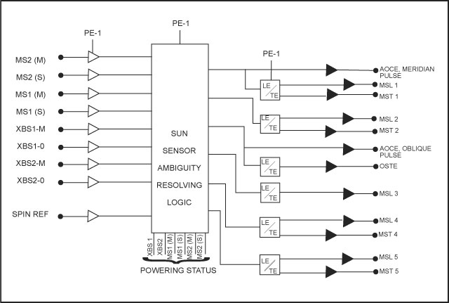
In the more complex case when both XBS sensors are on and the solar aspect angle is lower than 12.5 degrees, the following datation signals are generated:
| MSL1: | XBS | 1 meridian slit, 1st pulse leading edge |
| MST1: | XBS | 1 meridian slit, 1st pulse trailing edge |
| MSL2: | XBS | 1 meridian slit, 2nd pulse leading edge |
| MST2: | XBS | 1 meridian slit, 2nd pulse trailing edge |
| OSTE: | XBS | 1 oblique slit, trailing edge |
| MSL3: | MS1 | (main/standby), leading edge |
| MSL4: | XBS | 2 meridian slit, 1st pulse leading edge |
| MST4: | XBS | 2 meridian slit, 1st pulse trailing edge |
| MSL5: | XBS | 2 meridian slit, 2nd pulse leading edge |
| MST5: | XBS | 2 meridian slit, 2nd pulse trailing edge |
Next: Chapter 4.7.4 Onboard Generation of the SRP
Return to Chapter 4 Table of Contents
Return to Ulysses HISCALE Data Analysis Handbook Table of Contents
Updated 8/8/19, Cameron Crane
QUICK FACTS
Mission End Date: June 30, 2009
Destination: The inner heliosphere of the sun away from the ecliptic plane
Orbit: Elliptical orbit transversing the polar regions of the sun outside of the ecliptic plane