


Ulysses HISCALE Data Analysis Handbook
4.7.5 Onboard Generation of the Spin Segment Clock
The Spin Segment Clock (SSC) consists of 16384 pulses per spin period. The accuracy required is of plus or minus 6 pulses. The implementation is done by generating an SSC pulse after counting down M pulses at a frequency F.
The value of M is derived from the computed value of the SRP period and has a value equal to
M = Period*F/16384
The maximum frequency that could be used (technological considerations) is 917504 Hz. The actual time between two SRP, Q, is stored as a value on datation units (1/2048 sec.), and therefore the value of M is computed as
M = 7*Q/256
The value of M must be an integer number since it is used for loading a digital counter. This is the case for the nominal 5 rpm where the value of M is 672. In other cases where the value of M is not a pure integer, the error will be, in general, bigger than the requirements. For instance, if the period is 12.0178 sec. the value of M still will be 672 but the number of SSC pulses within two SRP will be
N = F* 12.0178/672 = 16408
The maximum error with this approach will be 24 SSC pulses. By rounding off the result of the division, the error will be plus or minus 12, still outside the requirements. Since F is fixed, the solution adopted consisted of varying the duration of the individual SSC pulses in such a way that the error is lower than 6 pulses. The implementation consists of loading an 8 bit shift register containing the remainder of the division. The register shifts with every SSC pulse and disables the first count if the bit is set and in practice stretches the width of the next SSC pulse by one count.
For example, if the value of M is 672 + 3/8, the shift register is loaded with 3, and of each 8 consecutive SSC's 5 will last 672 counts and 3 will last 673 counts, the mean being 672.375 and the number of SSC pulses during this spin period exactly 16384.
The diagram for the generation of the SSC is given in Figure 4.53. Table 4.17 gives the values of M, the SSC duration, and the maximum error for several spin rates.
Figure 4.53 Implementation of the SSC
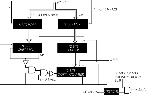
Table 4.17 Error on SSC
| rpm | M | Pulse Duration
(μsec) Pulse Period | SSC Error |
| 3 | 1120 | 1220.7 | ±0.9 |
| 1221.8 | |||
| 5 | 672 | 732.4 | ±1.5 |
| 733.5 | |||
| 20 | 3 | 183.1 | ±6.1 |
| 184.2 |
Next: Chapter 4.7.6 Reconstitution on the Ground of the SRP
Return to Chapter 4 Table of Contents
Return to Ulysses HISCALE Data Analysis Handbook Table of Contents
Updated 8/8/19, Cameron Crane
QUICK FACTS
Mission End Date: June 30, 2009
Destination: The inner heliosphere of the sun away from the ecliptic plane
Orbit: Elliptical orbit transversing the polar regions of the sun outside of the ecliptic plane