


Ulysses HISCALE Data Analysis Handbook
4.15 RTG Radiation Background Tests
The following is a memo from R. Gold to L. Lanzerotti, dated Sept. 28, 1994, on the status of the RTG radiation background tests.
REFERENCES:
1. Letter of June 29, 1979, to Rainer Grun from L. J. Lanzerotti on RTG induced backgrounds.
2. LAN-042-80, Initial Test of the Solar Polar LAN-2B Detector Head at the RTG Facility of JPL, by J. W. Kohl and R. E. Gold.
3. The RTG Background in the LAN Experiment and the Shielding Required to Control It, by R. E. Gold and G. M. Simnett, 1980.
4. LAN-076-84, LAN Medium Energy Noise and Background Counting Rates.
Following the concerns of high RTG background counting rates revealed in References 1 and 2, and the estimated shielding requirements of Reference 3, the LAN experiment was constructed with graded shields near most of the detectors. For the MF and M'F' detector pairs, the shields consisted of small areas of tungsten, pewter and iron to reduce the flux of gamma rays below ~200 keV. The B detector shield is a platinum-iridium collimator around the detector mount. In Reference 3, we estimated that the backgrounds below ~200 keV would be several counts per second while the background above 200 keV would total about 3 counts per second.
Background tests with a real RTG heat source were finally run in late August 1984 at Mound Laboratories in Miamisberg, Ohio. These tests followed three and a half months of delays caused by RTG acceptance testing problems at Mound. The RTG was the qualification model which has a flight design heat source and simulated thermocouple generator. The test was done in a low scattering facility at Mound with the orientation and separation of the RTG from LAN exactly as it will be in space. There was air between the RTG and LAN, but LAN was mounted in a small portable vacuum chamber to evaluate whether a significant part of the space environment would result from low energy electrons produced in the supporting structures outside the detectors. The distances from the near edge of the RTG (not including the mounting spool) to the LAN reference hole are shown in Table 4.21. The actual separations during the test could be verified to about ± 10mm. Data were taken in air, air with a bell jar, and in vacuum for approximately 20 minutes in each configuration.
The resulting count rates are listed in Table 4.22. The electronic backgrounds in the level 1 channels are uncertain. I have indicated my best guesses. Remember that the F' detector (E' channels) is noisy. However, the noise appears to be confined to E1' with perhaps some effect also in E2'. The observed counting rates in Table 4.19 are nearly insensitive to the vacuum system condition with the highest rates being observed in air. It appears that air is as effective in producing countable secondaries as the detector mounts, especially at low energy. Reference 3 predicted a background counting rate of ~3 counts per second integrated above 200 keV. The rates in Table 4.22 are better than that with integrated rates above 200 keV of ~0.06 to 1.3 counts per second. However, the RTG test was performed without a spacecraft while the estimates in Reference 3 assumed a significant contribution to the background from Compton scattering of the gamma rays by the Hydrazine filled fuel tank. Thus the test results appear to be consistent with the previous estimate. Reference 3 also predicted a relatively flat spectrum below 200 keV. The best data on the background energy spectrum was obtained using the LAN spectrum accumulator. The spectrum accumulator output in one 128 second cycle for the M' detector is shown in Figure 4.90. The channel numbers correspond to logarithmic energy bins from ~30 keV to ~5 MeV deposited energy. The lowest three channels are in the noise and should be ignored. The energy spectrum is indeed quite hard out to channels 14 or 15, which correspond to ~190 and 230 keV. It then falls off rapidly.
In summary, the background analyses in References 3 and 4 still appear valid and the RTG is expected to be the dominant source of background in the LAN experiment.
Table 4.21 Distance from RTG to LAN reference hole
| Spacecraft Coordinate System | RTG Coordinate System | Distance in mm |
| XRS | -YM | 1020 |
| YRS | ZM | 1791 |
| -ZRS | XM | 78 |
Figure 4.90 RTG Response in MFSA (M' Detector)
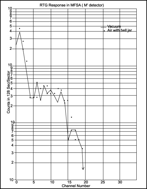
Table 4.22 Counting rates at Mound Laboratories RTG test
| Electronic Channel | Background | Vacuum | Air+Bell Jar | Air |
| P1' | >2 | 5.1 | 7.48 | 7.76 |
| P2' | ~0 | 0.86 | 0.91 | 0.99 |
| P3' | 0 | 0.75 | 0.74 | 0.74 |
| P4' | 0 | 0.39 | 0.43 | 0.43 |
| P5' | 0 | 0.11 | 0.12 | 0.13 |
| P6' | 0 | 0.009 | 0.007 | 0.009 |
| P7' | 0 | 0.002 | 0.000 | 0.0 |
| P8' | 0 | 0.0 | 0.003 | 0.0 |
| P1 | ? | 6.2 | 13 | 16.8 |
| P2 | 0 | 0.43 | 0.45 | 0.42 |
| P3 | 0 | 0.35 | 0.31 | 0.32 |
| P4 | 0 | 0.17 | ||
| P5 | 0 | 0.074 | ||
| P6 | 0 | 0.007 | ||
| P7 | 0 | 0.003 | ||
| P8 | 0 | 0.0 | ||
| E1' | Variable | 424 | 125 | 93 |
| E2' | ~0 | 1.0 | 0.94 | 1.1 |
| E3' | 0 | 0.60 | 0.57 | 0.61 |
| E4' | 0 | 0.34 | ||
| E5' | 0 | 0.11 | ||
| FP6 | 0 | 0.006 | ||
| FP7 | 0 | 0.003 | ||
| E1 | <0.5? | 0.70 | 0.66 | 0.69 |
| E2 | ~0 | 0.48 | 0.46 | 0.50 |
| E3 | 0 | 0.30 | 0.25 | 0.29 |
| E4 | 0 | 0.19 | 0.20 | |
| E5 | 0 | 0.07 | ||
| FP6 | 0 | 0.007 | ||
| FP7 | 0 | 0.003 |
| Electronic Channel | Background | Vacuum | Air+Bell Jar | Air |
| DE1 | <1? | 5.4 | 6.1 | 5.2 |
| DE2 | 0 | 0.59 | 0.63 | 0.62 |
| DE3 | 0 | 0.35 | 0.38 | 0.37 |
| DE4 | 0 | 0.23 | 0.25 | 0.25 |
Next: 4.16 Calibrations of Analog Housekeeping Data
Return to Chapter 4 Table of Contents
Return to Ulysses HISCALE Data Analysis Handbook Table of Contents
Updated 8/8/19, Cameron Crane
QUICK FACTS
Mission End Date: June 30, 2009
Destination: The inner heliosphere of the sun away from the ecliptic plane
Orbit: Elliptical orbit transversing the polar regions of the sun outside of the ecliptic plane