


Ulysses HISCALE Data Analysis Handbook
A17.4 LAN Spare - LEMS/LEFS LINEAR SAMA Crosstalk
Document Reference: Memo from D. E. Fort to R. E. Gold, August 28, 1984
Reference: S1I-1-036, "LAN Spare - LEMS/LEFS LINEAR Crosstalk" dated August 28, 1984 (Section A17.3)
Table A17-2 gives the test results for crosstalk in the SAMA channel. These tests were accomplished by injecting a fixed energy signal into a linear channel (with the Ca1 input shorted), and observing the output of the SAMA as each of the remaining linear channels was selected by the SAMA multiplexer. Obviously, the crosstalk is significant. Figure A17-9 shows the SAMA output waveform for two of the crosstalk cases.
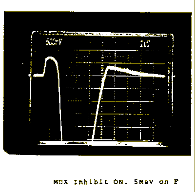
Since there is no significant crosstalk in the linear channels at 5 MeV (see Section A17.3), the crosstalk must arise within the SAMA channel itself. An additional test was conducted with the SAMA multiplexer inhibited (all switches open). The results are shown in Table A17-3. Figure A17-10 shows the SAMA ouput waveform when channel F is excited. Even with all switches open, the SAMA output is significant.
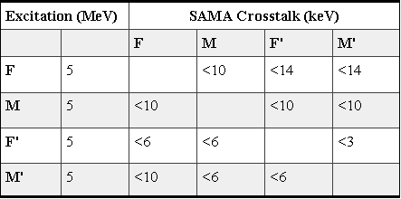
Table A17-2 SAMA crosstalk
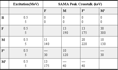
Table A17-3 SAMA crosstalk, MUX inhibited
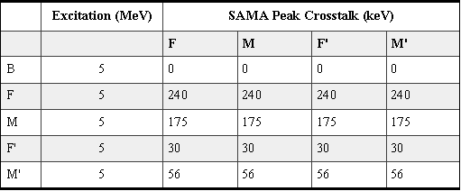
Figure A17-9 SAMA output waveform for 2 of the crosstalk cases
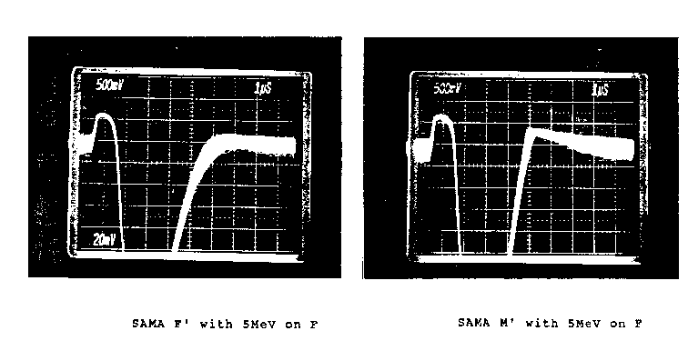
Figure A17-10 SAMA output waveform when channel F is excited
The crosstalk problem apparently arises due to parasitic capacitance within the multiplexer, and to the presence of a large series resistance in the signal path. For example, Figure A17-11a shows channel M' selected by the multiplexer, and Figure A17-11b shows the equivalent circuit assuming a simple shunt capacitance across each switch. F is taken to be the excited channel. A significant amount of the F signal could be coupled to the output depending on the value of the shunt capacitance.
Figure A17-11a MUX configuration with M' selected
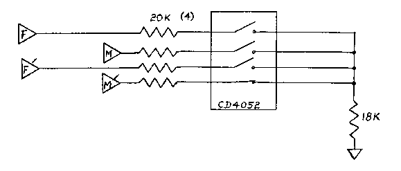
Figure A17-11b Equivalent circuit assuming feedthrough capacitance
Unfortunately, the magnitude of the crosstalk actually
observed is not in agreement with this simple model using
typical values of shunt capacitance given by the
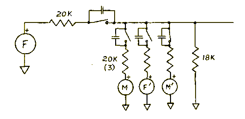
manufacturer (0.2 pF). Nevertheless, the model suggests a
possible solution which does in fact work. Suppose the
series resistance in the example of Figure A17-11 is changed
to 100W. Now the effective impedance at the multiplexer
output is 100 +RS (RS = switch ON
resistance, approx. 150W) instead of 10K, and the crosstalk
should decrease by nearly two orders of magnitude. Table
A17-4 shows the approximate values of crosstalk actually
measured for this configuration. (More precise measurements
will have to wait for a gain change in the log stage. See
item 2 below.)
Table A17-4 Approximate crosstalk w/100W
The penalties for making such a change are as follows:
- The large values of series resistance made independent adjustment of channel gain possible. The gains were matched so that a single SAMA response curve would serve for all channels. Making the resistance 100W eliminates this adjustment.
- The series resistance and the shunt resistance at the multiplexer output formed a divider which reduced signal levels 45%. This will now have to be accomplished at the log stage input by increasing the value of the 1.0K input resistor to approximately 2.21K.
- The series resistance protected the linear channels against shorts within the multiplexer.
Of these, the only serious consideration is item 1, and it should be noted that for SN003, the relative gains of the linear channels compare as follows (taking F1 as the standard):
F1 = 100%
M1 = 99+%
F1' = 99+%
M1' = 96%
Thus, the response curves for F1, M1 and F1' would be virtually identical, and the curve for M1' would be offset by only 5mV.
It should be noted that while a change to 100W drastically reduces crosstalk between channels when a channel is selected, the feedthrough with all switches open (multiplexer inhibited) will remain virtually unchanged from the values given in Table A17-3. However, since the PHA is also inhibited during these periods, no problem is expected.
Conclusion: Based on the above tests, it is recommended that the series resistance into the SAMA multiplexer (R121, R122, R123, R124) be reduced from its present value of approximately 20K to a new value of approximately 100W. In addition, the log amp input resistor must be changed from 1.0K to 2.21K to compensate for the change in the resistive divider ratio.
Next: A17.5 LAN Spare - CD Analog Crosstalk
Return to Appendix 17 Table of Contents
Return to HISCALE List of Appendices
Return to Ulysses HISCALE Data Analysis Handbook Table of Contents
Updated 8/8/19, Cameron Crane
QUICK FACTS
Mission End Date: June 30, 2009
Destination: The inner heliosphere of the sun away from the ecliptic plane
Orbit: Elliptical orbit transversing the polar regions of the sun outside of the ecliptic plane