


Ulysses HISCALE Data Analysis Handbook
Appendix 18. Preliminary Solar Polar Magnet Study
A18.2 Test Set-Up
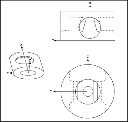
To survey the magnetic field intensity, a test set-up as shown in Figure A18-1 was used. Both the yoke holder fixture and the Hall-effect probe fixture were mounted on a rigid baseplate to maintain a constant positional relationship. The yoke fixture has a linear motion device providing one degree of freedom with a vernier scale that has an uncertainty in reading the scale of ± 0.002 inches. The probe fixture provides two degrees of freedom perpendicular to each other and to that of the yoke fixture, with an uncertainty in the readings of ± 0.0005 inches. Together, the fixtures provide three degrees of freedom within the orthogonal axis system shown in Figure A18-2. For all the measurements presented in this report, this is the coordinate system used.
Figure A18-1 Magnet field survey mechanical setup
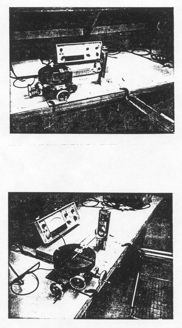
Figure A18-2 Sketch to indicate axis orientation with respect to magnets
The instrument used to measure the magnetic field intensity in the yoke is a Bell Gaussmeter model 610 with a Bell Hall-effect probe model HTB-1-0608. The uncertainty in the location of the sensing element within the probe is ± 0.07 inches in the axial direction of the probe and ± 0.004 inches in the transverse direction. The probe itself was aligned visually with the origin of the yoke coordinate system prior to taking the field measurements. An estimate of the error involved in the resetability of the probe to the origin each time would be approximately ± 0.002 inches.
The Gaussmeter/probe combination was zeroed each time prior to a series of measurements. This was accomplished with a zero-field chamber (a cylinder of high permeability material) surrounding the probe. Upon removal of the zero-field chamber, the instrument would read an earth field of approximately + 0.40 Gauss. This background field was not subtracted from the yoke field measurements to be presented. The units of all the field measurements presented in this report are in Gauss. The accuracy of the meter reading due to size of the smallest increment, needle width, etc., is estimated to be approximately ± 3% of the value of the reading.
In general, it is estimated that the total uncertainty in each of the magnetic field data points presented in this report is approximately ± 5%.
To test if electrons in the energy range desired would impact the solid-state detector surface in the yoke, a preliminary electron calibration was run on the electrostatic accelerator at NASA/Goddard SFC. The point of electron beam impact was viewed on a glass slide coated with ZnS fluorescent powder through a window vacuum port. The glass slide was indexed with 0.1" graduations and was located at the approximate position of the solid-state detector in the yoke.
The magnet/yoke assembly was mounted on a test fixture provided by UCB and modified by APL to restrict the degrees of freedom to one degree of translation (the "Z" axis). The test fixture was mounted on a vacuum feed-thru assembly which provided rotational motion (q) and vertical linear motion (Y). A sketch to indicate the various coordinate systems and their inter-relationship in the GSFC vacuum system is provided in Figure A18-3.
Figure A18-3 Sketch to indicate yoke/electron beam orientation on electrostatic accelerator at NASA/GSFC
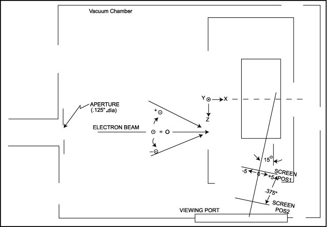
The electron beam entered the vacuum chamber through a 0.125 inch collimating aperture--some runs were made with a 0.50 inch diameter aperture, but are not discussed in this report. The yoke test fixture was oriented in the vacuum chamber so that the electron beam was targeted at some point in the front surface of the yoke (Y, Z plane; X = 0). The yoke was then rotated about the target point so that the beam would enter the yoke at some angle q measured from a perpendicular to the front surface of the yoke. The location of the beam image on the phosphor screen was then recorded.
The uncertainties inherent to the electron beam measurements are, in general, much larger than for the field survey. It is estimated that the uncertainty in the relationship between the center of the beam and the target position is approximately ± 0.03 inches due to the yoke fixture mounting technique, the way the yoke cover plate is mounted and the visual alignment of the aperture and the yoke centerline. The position of the phosphor screen along the 15º line to the magnet assembly probably has an uncertainty of approximately ± 0.03 inches in its approximation to the position of the solid-state detector surface.
In general, it is estimated that the uncertainty in the relationship between the incoming electron beam and resulting electron beam image on the phosphor screen could be about ± 0.50 inches.
Next:
A18.3 Data
Return to Appendix 18 Table of Contents
Return to HISCALE List of Appendices
Return to Ulysses HISCALE Data Analysis Handbook Table of Contents
Updated 8/8/19, Cameron Crane
QUICK FACTS
Mission End Date: June 30, 2009
Destination: The inner heliosphere of the sun away from the ecliptic plane
Orbit: Elliptical orbit transversing the polar regions of the sun outside of the ecliptic plane