


Ulysses HISCALE Data Analysis Handbook
Appendix 2. User's Guide to LAN360
A2.5 LEMS and LEFS Differences
Typical values of deflect and foilfact for the IDF.DAT version 1.03 are 0.5 and 1.2, respectively. These values are not = 1.0 because of inaccurate energy ranges and geometry factors in Version 1.03 of IDF.DAT. These values will probably be improved (and will certainly be different) with the next version of IDF.DAT, and new values of deflect and foilfact will need to be determined. (Preliminary values for IDF.DAT 1.13 are deflect = 0.9 and foilfact = 1.0.)
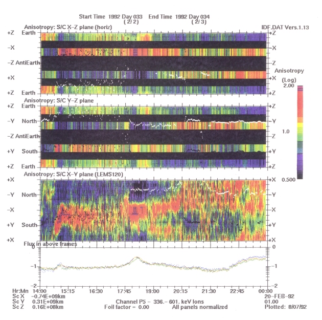
Foilfact can be set to 0.0 in order to plot only the low energy ion channels (LEMS30 and LEMS120; see Table A2-1). In this case, the LEFS channels will plot as black.
There are times when the LEMS or the LEFS channels (P5-7) appear to be saturated with respect to the other. Figure A2-5, as Ulysses enters the Jupiter magnetosphere, shows several examples. If the LEMS are higher than the LEFS (e.g., day 33, ~18-19 UT), it may be due to large fluxes of low energy heavy ions, which would be stopped by the foil on the LEFS detectors. If the LEFS are higher than the LEMS (e.g., day 33, ~2230-2400 UT), this indicates large numbers of electrons, as the LEFS channels also measure electrons. If one is not sure of the values to use for foilfact or deflect, or of the balance between the LEMS and LEFS, initial plots should be run without smoothing (smooth=0) in order to determine the factors without distraction.
Figure A2-5 LAN plot
for channel P5 for hours 14-24 UT on day 33, 1992. In this
time interval there are heavies in the LEMS30 and LEMS120
detectors around 1800 UT, and electrons in the LEFS
detectors after about 2230 UT.
(a) Plot with smooth = 0. The option for no smoothing
clearly shows the relative saturation in the LEFS (electron)
channels after ~2130 UT.
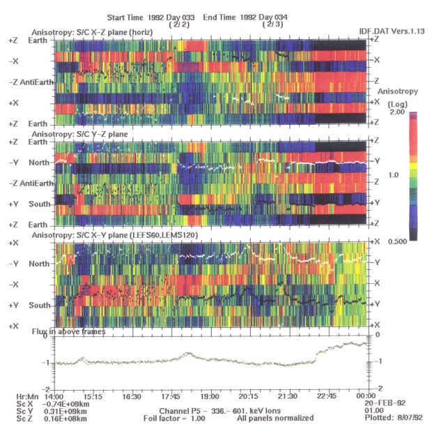
Figure A2-5b Plot with smooth = 1. It is also obvious here that the LEFS channels are very high compared to the LEMS.
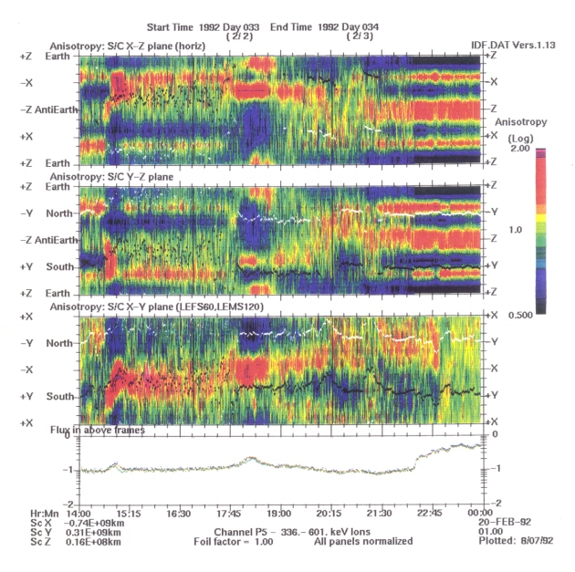
Figure A2-5c Setting foilfact to 0.0 allows the ion anisotropies in this energy range after 2130 UT to be seen.
A2.5.1 Electron Fill
Under certain circumstances, when the electrons are organized by the magnetic field, it may make a 'prettier picture' if the LEFS60 area is filled by the electrons measured in LEMS120 shifted by 180° in azimuth. Except in special cases, this option should not be used.
Next: Appendix 2.6 Other Features
Return to Appendix 2 Main Table of Contents Page
Return to Ulysses HISCALE Data Analysis Handbook Table of Contents
Updated 8/8/19, Cameron Crane
QUICK FACTS
Mission End Date: June 30, 2009
Destination: The inner heliosphere of the sun away from the ecliptic plane
Orbit: Elliptical orbit transversing the polar regions of the sun outside of the ecliptic plane