


Ulysses HISCALE Data Analysis Handbook
Sector Flag Delays. The delay pointers and values refer to the delay between a sector flag occurring and the beginning of the routines which load data and reset accumulators. These delays occur while the processor executes other routines; if the delay for a given sector is less than approximately 0.39% of a sector duration, it will be considered as no delay. Spin group numbers will range from 0001 (first group) to 1010 (tenth group). Sector numbers will range and delay pointers will be zeroed at the end of each cycle.
Delay Values. When the experiment is operating in the sun sectoring mode, the delay value will be in terms of the 16384 x spin clock, with each value increment representing 8 pulses, or 8/(16384/8) x 100% = 0.39% of a sector duration. When the experiment is operating in the time sectoring mode, the delay value increment represents 2048 pulses, or 17.86 msec (about 1.2% of a sector duration).
The delay value will range from 0000 (no delay) to 1111 1110 (0.99 sectors too long -- this should never occur).
Validity Telltales. Changes in the S/C spin rate and therefore the sectoring mode are expected infrequently, perhaps a few times per day, but the validity of data at those times must be telltaled to prevent systematic errors in the analysis. The data system will test conditions of sectoring mode and telemetry mode to generate validity bits in bytes 15 and 16 of the status trailer. In general, data is considered invalid when, while in the slower 3 telemetry rates, it is time sectoring at any time other than during the last spin of a spin group. Spin group numbers are shown in Figure 4.42. A one indicates invalid data; zero, valid data.
First and Last Spin Indicators. Because the timing relations between data input and output can vary widely, it may be necessary at times to end data collection before the last expected spin or to drop the first spin group of data. Byte 16 of the status trailer defines the last spin of the current cycle and the first group of the next cycle. A zero LSB indicates group 1 starts valid data collection, a one indicates group 2.
The last valid spin (not spin group) of the cycle is shown below as a function of the telemetry mode.
| Telemetry Mode ID | Last Spin Definition | |
| 00 | S | S ranges from 0-9 (spins 1-10) |
| 01 | S-4 | S ranges from 0-19 (spins 1-20) |
| 10 | S-24 | S ranges from 0-39 (spins 1-40) |
| 11 | S-64 | S ranges from 0-79 (spins 1-80) |
Expected values are (decimal) 9, 19, 39, or 79 under steady state conditions.
Sectoring Mode Bits. The data system has the capability to determine whether the S/C spin rate is within certain bounds and to adjust the sectoring mode accordingly. This capability, generated too quickly for accurate sampling or too slowly to do so, is telltaled in bytes 17 and 18 of the status trailer. A one indicates time sectoring; a zero indicates sun sectoring. Spin group numbers are shown in Figure 4.42.
The remainder of the digital housekeeping channels are used as shown in Figure 4.43. SP1-7 are sun pulse timing changes for this cycle, for spin groups 1-7. For SP8-10 the sign will be 1 if the sun pulse occurred before the 16384th pulse of the 16384 x spin clock; zero if it occurred afterward. An increment of the mantissa will represent 1 count of the 16384 x spin clock. From this information one can determine the degree to which the eight sectors of a spin were truncated, during times of transient spin rate. The values which indicate that the 8th sector was dropped are defined in sections 4.5.17 and 4.6.
Figure 4.43 Digital housekeeping format, channels 2-4
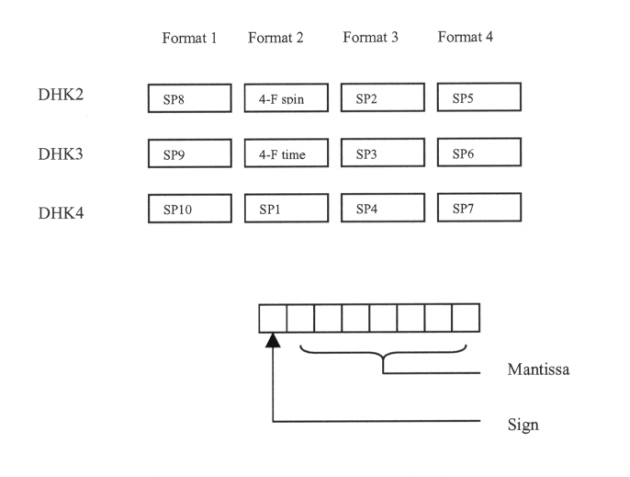
4-F SPIN is the spin count (0 - 79) at the four-format epoch. It is used to reference time sectored data to the four-format pulse and therefore to the sun.
4-F TIME adds precision to this measurement. The three MS bits represent the completed sector count (0 to 7), and the five LS bits represent counts based on the HF clock. The value of the LS bit is 71.4 msec. The five LS bits are valid only when time sectoring is used.
4.5.13 Digital Housekeeping Data
Four bytes of housekeeping data are generated during each S/C format, or a total of 16 bytes during the experiment data format. Of the four channels, DHK1 is dedicated to the calibrator MUX address. This address is binary number from 0 to 127. The LSB indicates whether the lower (0) or upper (1) threshold of a detector is being calibrated. The resulting threshold voltage appears on an analog housekeeping line. The next six bits (B1-B6) specify the discriminator being calibrated (not used: deleted from flight instrument).
Next: Chapter 4.5.11: Sectoring
Return to Chapter 4 Table of Contents
Return to Ulysses HISCALE Data Analysis Handbook Table of Contents
Updated 8/8/19, Cameron Crane
QUICK FACTS
Mission End Date: June 30, 2009
Destination: The inner heliosphere of the sun away from the ecliptic plane
Orbit: Elliptical orbit transversing the polar regions of the sun outside of the ecliptic plane