


Ulysses HISCALE Data Analysis Handbook
Data from the MFSA and the rate accumulators is summed and logarithmically compressed. Data from the CA PHA is sorted by a priority schedule during slow telemetry modes. The data -1 and data -2 flags, which call the rate and CA processing routine and the MFSA summation routine respectively, are set at the end of each valid sector of data accumulation. The data -3 flag, which calls the MFSA compression and output routine, is set at the end of each data collection cycle. The functions of each processing routine are described in this section.
Rate Data Processing. At the end of each sector, 24 bit data from each of 48 channels is summed with the contents of a summation buffer. At times appropriate for each channel, the results are compressed to 8-bit counts by an algorithm described in space for that channel and the sector is then zeroed.
Accumulation Periods. Rate data is collected over one of five periods for a given telemetry mode. The periods are the following:
a) One sector duration of one spin, for channels P'1 - P'5 and E'1-E'4.
b) Two continuous sectors duration of one spin, for channels P1-P4 and E1-E4.
c) One sector duration for each spin of a spin pair, for channels P'6-P'8, E'5, FP'6, FP'6, FP'7, D2, D2a, D3, D4, and W1-W8.
d) Two continuous sectors duration for each spin of a spin pair, for channels P5-P8, E5, FP6, FP7, and DE1-DE4.
e) The entire duration of a spin pair, for the multiplexed channels S1 and S2.
The accumulations over sector pairs combine the sums over sectors 1 and 2, 3 and 4, 5 and 6, and 7 and 8, where sector one starts a commendable duration after the occurrence of the sun pulse. During slow telemetry rates, the same method applies, except that data of periods a and b are summed once a spin group (2n spins, where n is the mode ID), and data of periods c, d, and e are collected over a pair of spin groups.
MFSA Data Processing. MFSA data is accumulated according to one of the 8 schedules. Each schedule is active for the duration of the data collection cycle, regardless of the telemetry mode. At the end of the appropriate sectors, as indicated by the schedule, 8-bit data from each of 32 channels are summed into one of four, 16-bit x 32 buffers. This routine may also be called when an overflow of one of the 8-bit counts occurs in the MFSA hardware.
An overflow of the 16-bit summation is telltaled in the status trailer, indicating the data group and the spin group for which the overflow occurred. After an overflow occurs, summation for all data groups stops for future sectors until the end of the data cycle. The number of the current MFSA schedule is telltaled in the status preamble.
MFSA Downtime. The data system processes interrupts from the MFSA in addition to the regularly scheduled loads. As more interrupts occur, a greater part of the accumulation time is unused while the MFSA waits for the data system to notice and read it. The effect of these delays is tabulated below, for given rates into a single energy channel:
| Rate per Channel (Events/Second) | % of Time Not Accumulating |
| 50 | 0.6 |
| 100 | 0.6 |
| 250 | 1.0 |
| 500 | 1.4 |
| 1000 | 2.8 |
| 2000 | 6.1 |
| 3000 | 10.2 |
| 3880 | 12.4 |
MFSA Overflow Telltales. The final byte of the status trailer allows the detection of an overflow of a single MFSA data group (A, B, C, or D). The two LSB's indicate the data group, and the next four bits indicate the spin group during which the overflow occurred. The spin groups are defined as 0001 = group 1, 1010 = group 10, and so forth. Data groups are defined as follows (see the section MFSA Schedule):
| Data Group | MSB LSB |
| A | 00 |
| B | 01 |
| C | 10 |
| D | 11 |
A zero fill in the spin group nibble indicates that no overflow occurred.
The data system sequences the priority schedule provided to the CA PHA. The CA PHA, designed by C.R. Tielens, uses this information to select which events will be retained as data, based on the table shown in Figure 4.41. For example, if all four event types occur while using schedule 11 (Sl, SO), then data for the O and Fe events will be retained and provided to the data system at the end of the sector. The data system notes that the event of the lowest priority was type O, and for the corresponding sector of the next spin group assigns the appropriate schedule bits. The schedules for the 8 sectors of a spin are independent of each other.
Slow Telemetry Rates. During slower telemetry rates, the schedule for each sector is maintained for all the spins of a spin group. During these times, the number of spins within a format has increased but the amount of data to be output must be constant. So, at the end of each sector, the data system chooses two events to be retained from the four available: two events from the last time plus two new ones ( i.e., the sorting is done sequentially, rather than collecting data for each spin of a group and then sorting).
The two events to be retained in this case are the two of the highest priority, based on the current schedule. So within a spin group, the two highest priority events are retained for output; of these, the lowest priority event determines the schedule for the next spin group. The priority schedule was designed by R.E. Gold using computer simulations of probable event scenarios, and attempts to provide even sampling rates for all data types.
Compression
Log Compression Routine. This routine compresses 16-bit (MFSA) and 24-bit (rate) data to an 8-bit word, composed of a 4-bit exponent followed by a 4-bit mantissa. The value of the data is (Mantissa + 16) x 2 (Exponent-1), except that when the exponent is zero, then the value equals the mantissa. The word precision of the data is
+1 24 = +1/16 = +6%, -0%.
-0 -0
Table of Values
The binary and decimal value ranges for each exponent are shown below:
| Exponent | Binary Range | Decimal Range |
| 0 | 000000-00000F | 0-15 |
| 1 | 000010-00001F | 16-31 |
| 2 | 000020-00003F | 32-63 |
| 3 | 000040-00007F | 64-127 |
| 4 | 000080-0000FF | 128-225 |
| 5 | 000100-0001FF | 256-511 |
| 6 | 000200-0003FF | 512-1023 |
| 7 | 000400-007FF | 1024-2047 |
| 8 | 000800-000FFF | 2048-4093 |
| 9 | 001000-001FFF | 4096-8191 |
| A | 002000-003FFF | 8192-16383 |
| B | 004000-007FFF | 16384-32767 |
| C | 008000-00FFFF | 32768-65535 |
| D | 010000-01FFFF | 65536-131071 |
| E | 020000-03FFFF | 131072-262143 |
| F | 040000-07FFFF | 262144-524287 |
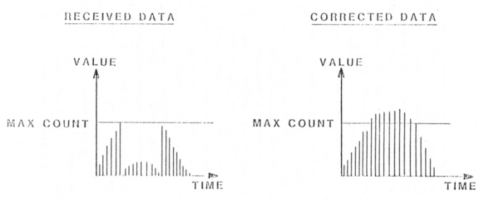
Overflow. MFSA data is limited to 16 bits and therefore does not exceed the limits of the log compression routine. Rate data counts may be as high as 223-1. The MS Byte of rate data will be treated modulo (220-1), so that the modulus may be added to the indicated value to obtain the actual value, when indicated by the time history of that channel. A graphical depiction of the result is shown in Figure 4.44.
Figure 4.44 obtaining rate data values by adding modulus
Next: Chapter 4.5.15: Timing
Return to Chapter 4 Table of Contents
Return to Ulysses HISCALE Data Analysis Handbook Table of Contents
Updated 8/8/19, Cameron Crane
QUICK FACTS
Mission End Date: June 30, 2009
Destination: The inner heliosphere of the sun away from the ecliptic plane
Orbit: Elliptical orbit transversing the polar regions of the sun outside of the ecliptic plane