


Ulysses HISCALE Data Analysis Handbook
4.7.1 Sun Sensor Configuration
Two types of sun sensors are used on the Ulysses spacecraft. The first type contains a single meridian slit (the meridian plane contains the spacecraft z axis); this type of sensor is denominated MS (meridian slit). The second type contains two slits, one on the meridian plane and the other on an inclined plane at nominally 14 degrees from the meridian; these sensors are denominated XBS (cross beam slit).
The MS sensors are internally redundant and are provided with two optical heads which are mounted parallel to each other on a common flange. Their field of view is fan shaped with a cross-extension of view (CEOV) of 1 degree and a length-extension of view (LEOV) of 70 degrees on one side of the optical axis. This provides a sharp cut-off. Each head is connected to an independent electronic channel, thus providing an internally redundant unit where only one of the two (main or standby) sections is switched on.
The field of view of each of the optical heads of the XBS sensors is also fan shaped, with the same CEOV as the MS1 but a LEOV of +60 and -70 degrees with respect to the optical axis. The XBS sensors are not internally redundant and therefore two equivalent sensors, XBS1 and XBS2, are installed on the spacecraft.
Figure 4.48 shows the sensor configuration.
Figure 4.48 Sun sensor configuration
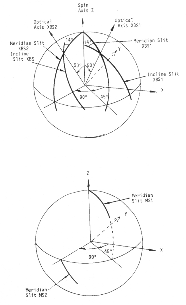
The MS1 sensor is mounted with its optical axis at 1 degree off the z axis (spin axis). For solar aspect angles in the range 1 to 61, a single pulse per spin is obtained. The MS1 sensor is rotated by 5 degrees about z with respect to the XBS1, and therefore the MS1 pulse precedes the XBS1 meridian sun pulse. This is used to differentiate between the two XBS meridian pulses obtained for small solar aspect angles.
The MS2 sensor is mounted with its optical axis at 90 degrees to the spin axis and it provides a single sun pulse for solar aspect angles in the range 90 to 150 degrees.
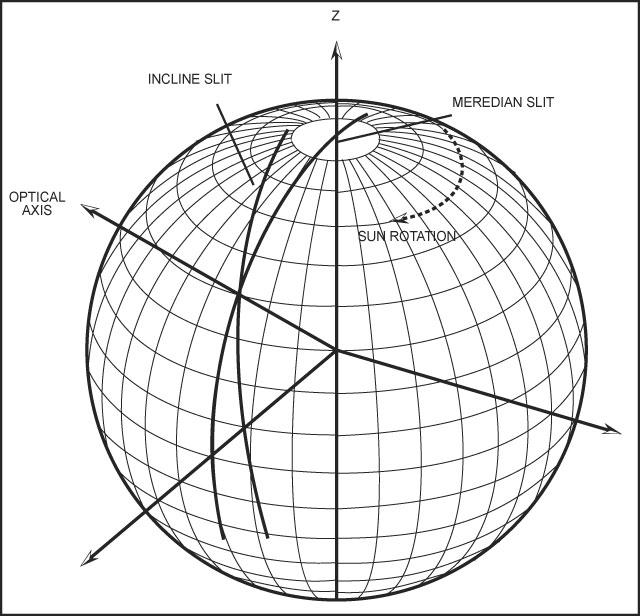
The XBS sensors are mounted on brackets so that their optical axes are at 50 degrees to the spin axis. The meridian slit extends for 60 to 70 degrees on either side of the optical axis. For solar aspect angles of less than 10 to 20 degrees two sun pulses per spin are obtained from the meridian slit; for larger solar aspect angles a single meridian sun pulse is obtained. The inclined slit, rotated by 14 degrees with respect to the meridian slit, provides a sun pulse for solar aspect angles in the range 11 to 115 degrees. Figure 4.49 shows the XBS geometry.
The functions performed by the sun sensors are:
XBS1, XBS2 - Spin reference pulse determination (processing carried out in the Data Handling Subsystem) from the meridian slit pulses.
Solar aspect angle determination in one of the two modes depending on the SAA. If the SAA is less than about 15 degrees, the angle between the leading and trailing edges of the meridian pulse is measured and processed. For larger SAA the angle from the meridian and inclined slit is measured.
Occasionally, with both sensors switched on, the meridian crossings are processed on ground to determine the spacecraft principal axis tilt.
MS1 - Differentiate between the two XBS meridian sun pulses at small solar aspect angles.
MS2 - Generate the spin reference pulse for solar aspect angles outside the field of view of the XBS sensor.
Next: Chapter 4.7.2 Sun Sensor Electronics
Return to Chapter 4 Table of Contents
Return to Ulysses HISCALE Data Analysis Handbook Table of Contents
Updated 8/8/19, Cameron Crane
QUICK FACTS
Mission End Date: June 30, 2009
Destination: The inner heliosphere of the sun away from the ecliptic plane
Orbit: Elliptical orbit transversing the polar regions of the sun outside of the ecliptic plane