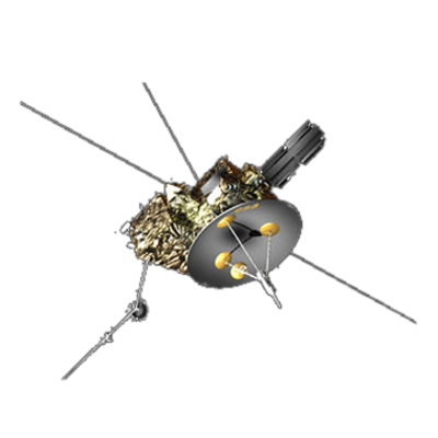
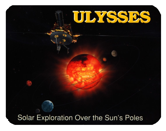
ULYSSES
Ulysses HISCALE Data Analysis Handbook
- Table 1.1 LEMS detector system summary
- Table 1.2 LEFS detector systems summary
- Table 1.3 Composition Aperture summary
- Table 1.4 Geometrical factors and nominal backgrounds
- Table 1.5 M and F Spectrum Accumulator (MFSA) summary
- Table 1.6 Common HISCALE prefixes and suffixes
- Table 2.1 Files in the root directory for ULS CD-ROMs
- Table 2.2 Files in the index subdirectory
- Table 2.3 Files in the document subdirectory
- Table 2.4 EDR SIS acronyms
- Table 2.5 Recommended CD-ROM drives and driver software
- Table 2.6 ISPM SFDU primary header format
- Table 2.7 ISPM SFDU primary header
- Table 2.8 ISPM SFDU secondary header format
- Table 2.9 ISPM SFDU secondary header
- Table 2.10 ISPM SFDU tertiary header format
- Table 2.11 ISMP EDR tertiary header
- Table 2.12 EDR clocks and counters
- Table 2.13 LAN EDR data block format
- Table 2.13a HISCALE science data block
- Table 2.14 Science data rate and CA one spin pair
- Table 2.15 Description of differences between the HISCALE and EPAM SFDU headers as defined by the Ulysses Software Interface Specification Experiment Data Record
- Table 2.16 HISCALE record header definition
- Table 2.17 HISCALE rate block
- Table 2.18 LAN Pulse Height Archive block
- Table 2.19 LAN MFSA block
- Table 4.1 HISCALE assembly FOV calculation summary
- Table 4.2 Parts list for LAN2A assembly
- Table 4.3 Properties of commercial window materials
- Table 4.4 Unit mass absorptions of various window materials
- Table 4.5 HISCALE discriminator levels
- Table 4.6 LEMS30 parameters and logic
- Table 4.7 LEMS120 parameters and logic
- Table 4.8 LEFS60 parameters and logic
- Table 4.9 Parameters and logic for LEFS150
- Table 4.10 Composition Aperture (WART) parameters and logic
- Table 4.11 Proton and electron passbands
- Table 4.12 LEFS detector passbands for selected ion species
- Table 4.13 LEMS proton and ion passband summary
- Table 4.14 WART passband
- Table 4.15 Science data rate and CA one spin pair (same as Table 2.14)
- Table 4.16 Command Structure
- Table 4.17 Error on SSC
- Table 4.18 Geometric factors for deflected electrons trial 10 B-field
- Table 4.19 Deflected electron geometrical factors
- Table 4.20 LEFS60 and 150 electron passbands
- Table 4.21 Distance from RTG to LAN reference hole
- Table 4.22 Counting rates at Mound Laboratories RTG test
- Table 5.1 Minimum count rates in each channel for interval number 1
- Table 5.2 Minimum count rates in each channel for interval number 3
- Table 5.3 Minimum count rates in each channel for interval number 4
- Table 5.4 Minimum count rates in each channel for interval number 5
- Table 5.5 Minimum count rates in each channel for interval number 6
- Table 5.6 WART channels lowest levels
- Table 5.7 Minimum count rates in each channel for entire mission
- Table 5.8 Background rates used for the latitude variation study
- Table 5.9 Change in non-event rates from 30° to 60° latitude 5-7
- Table 5.10 LAN calibration sources
- Table 5.11 LAN calibration history
- Table 5.12 Wart energy ranges
- Table 5.13 Average count rates during cover-closed calibrations
- Table 5.14 PHA counts/percentages
- Table 5.15 Track dump output 92049
- Table 5.16 MFSA spectral dump output 90319, 2010-2210
- Table 5.17 MFSA spectral dump output 94091, 1030-1330
- Table 5.18 LAN cover close/open timings
- Table A2-1 Available LAN channels for LAN360
- Table A2-2 Available WART channels (XY plane only)
- Table A2-3 Channels and sectors used for ion anisotropy plots
- Table A3-1 Ulysses investigations contributing to the CDF
- Table A3-2 Ulysses CDF data channels
- Table A3-3 CDF plots
- Table A4-1 ULS SFDU primary and secondary header description
- Table A4-2 ULS SFDU tertiary header description
- Table A4-3 BAM CDF data block format
- Table A4-4 GLG CDF data block format
- Table A4-5 KEP CDF data block format
- Table A4-6 LAN CDF data block format
- Table A4-7 SIM CDF data block format
- Table A4-8 STO CDF data block format
- Table A4-9 HED header format
- Table A4-10 HED CDF data record format
- Table A7-1 ULS SFDU primary header format
- Table A7-2 ULS SFDU secondary header
- Table A7-3 ULY EDR tertiary header format
- Table A7-4 EDR clocks and counters
- Table A7-5 Relationship between data rate, number of minor frames, time and SCLK
- Table A7-6 LAN EDR data block format
- Table A7-7 VOL1 label contents
- Table A7-8 HDR1, EOV1, EOF1 label contents
- Table A7-9 HDR2, EOV2, EOF2 label contents
- Table A8-1 Experiment designator versus number
- Table A8-2 Mission phase code
- Table A8-3 SEDR type code
- Table A8-4 ULS SEDR primary and secondary SFDU header definition
- Table A8-5 ULS SEDR tertiary SFDU header definition
- Table A8-6 ULS SEDR data format
- Table A9-1 Deflected electron energy thresholds
- Table A9-2 Geometric factors for deflected electrons, Trial 10 B field
- Table A9-3 Geometric factors for deflected electrons combined average of notch one and two
- Table A9-4 LEFS electron passbands
- Table A9-5 Detector coordinates
- Table A9-6 Plane number, number of vertices, and plane coefficients A, B, C, and D in the equation of a plane
- Table A9-7 Coordinates of detector segmentation
- Table A9-8 B-field maps, experimental and simulated, trials 6 and 10, midplane
- Table A9-9 Same as Table A9-8, except for Z = 0.1" plane
- Table A9-10 Same as Table A9-8, except Z = -0.1" plane
- Table A9-11 B-field maps, experimental and simulated, trials 4 and 11, midplane
- Table A9-12 Same as Table A9-11, except Z = 0.1" plane
- Table A9-13 Same as Table A9-11, except Z = -0.1" plane
- Table A9-14 B-field maps, experimental and simulated, trials 5 and 12, midplane
- Table A9-15 Same as Table A9-14, except Z = 0.1" plane
- Table A9-16 Same as Table A9-14, except Z = -0.1" plane
- Table A9-17 B-field maps, experimental and simulated, trials 3 and 13, midplane
- Table A9-18 Same as Table A9-17, except Z = 0.1" plane
- Table A9-19 Same as Table A9-17, except Z = -0.1" plane
- Table A9-20 Escaped particle counts for segmented detector area
- Table A10-1 HISCALE deflected electron detector energy thresholds
- Table A10-2 DE detector channel-integrated geometrical factors
- Table A10-3 Escaping trajectories (Radzimski model)
- Table A10-4 Escaping trajectories (Neubert model)
- Table A10-5 Escapes without scattering
- Table A12-1 UDS User List
- Table A12-2 UDS User List
- Table A12-3 UDS User List
- Table A16-1 Energy bins
- Table A16-2 LAN track record definition
- Table A16-3 COMP.DAT definitions
- Table A16-4 Definition of SEEMFSA.DAT
- Table A16-5 Definition of SPECTIME.DAT
- Table A16-6 Definition of SPECPLOT.DAT
- Table A16-7 Definition of LANSPECT.DAT
- Table A17-1 LEMS/LEFS LINEAR crosstalk
- Table A17-2 SAMA crosstalk
- Table A17-3 SAMA crosstalk, MUX inhibited
- Table A17-4 Approximate crosstalk w/100W
- Table A18-1 Solar Polar magnetic field survey yoke: SST416/APL (w/o hole). Magnetic configuration I. Magnetic field (Gauss)
- Table A18-2 X vs. Z scan at Y=-0.1" for magnets 03 and 04
- Table A18-3 X vs. Z scan at Y=0.0" for magnets 03 and 04
- Table A18-4 X vs. Z scan at Y=+0.1" for magnets 03 and 04
- Table A18-5 X vs. Z scan at Y=-0.1" for magnets 05 and 06
- Table A18-6 X vs. Z scan at Y=0.0" for magnets 05 and 06 (10 July 1980)
- Table A18-7 X vs. Z scan at Y=+0.1" for magnets 05 and 06
- Table A18-8 X vs. Z scan at Y=0.0" for magnets 05 and 06 (31 July 1981)
- Table A18-9 X vs. Z scan at Y=-0.1" for magnets 09 and 10
- Table A18-10 X vs. Z scan at Y=0.0" for magnets 09 and 10
- Table A18-11 X vs. Z scan at Y=+0.1" for magnets 09 and 10
- Table A18-12 X vs. Z scan at Y=-0.2" for magnets 07 and 08
- Table A18-13 X vs. Z scan at Y=-0.1" for magnets 07 and 08
- Table A18-14 X vs. Z scan at Y=0.0" for magnets 07 and 08
- Table A18-15 X vs. Z scan at Y=+0.1" for magnets 07 and 08
- Table A18-16 X vs. Z scan at Y=+0.2" for magnets 07 and 08
Next: List of Figures
Return to Ulysses HISCALE Data Analysis Handbook Table of Contents
Updated 8/8/19, Cameron Crane
QUICK FACTS
Manufacturer:
ESA provided the Ulysses spacecraft, NASA provided the power
supply, and various others provided its instruments.
Mission End Date: June 30, 2009
Destination: The inner heliosphere of the sun away from the ecliptic plane
Orbit: Elliptical orbit transversing the polar regions of the sun outside of the ecliptic plane
Mission End Date: June 30, 2009
Destination: The inner heliosphere of the sun away from the ecliptic plane
Orbit: Elliptical orbit transversing the polar regions of the sun outside of the ecliptic plane


